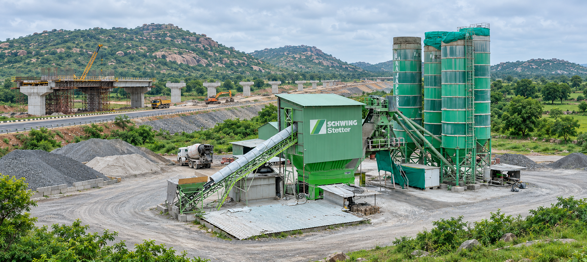
The Schwing Stetter HN 4.0 is a horizontal concrete mixing plant from the modular HN series, built around a 6.00 / 4.00 m³ twin-shaft mixer. It produces 148 m³/h of compacted concrete on a 30-second mixing cycle, with a maximum output of 190 m³/h. From the HN 4.0 size upwards the plant is supplied only in the inclined belt conveyor execution.
Capacity148 m³/h
Max. Capacity190 m³/h
Mixer Size6.00 / 4.00 m³
Connected Load275 kVA
Aggregate Weighing10,000 kg
Water Weighing1,125 kg
Key Highlights
Plant Type
Horizontal
Mixer Type
Twin-shaft
Mixer Size
6.00 / 4.00 m³
Capacity (30 s)
148 m³/h
Max. Capacity
190 m³/h
Aggregate Weighing
10,000 kg
Cement Weighing
2,100 kg
Water Weighing
1,125 kg
Admixture Weighing
Optional
Discharge Height
4.2 m
Mixer Platform
5.9 m
Aggregate Types
4 – 8
Cement Types
Up to 7
Silo Compartments
4 – 8
Aggregate Feed
Inclined belt
Connected Load
275 kVA
Aggregate Storage
32 / 36 m³
Belt Inclination
16° – 24°
Coarse Grain Option
Up to 160 mm
Water Connection
DN 80
Specifications
Detailed technical specifications for the Schwing Stetter HN 4.0 horizontal concrete batching plant
Capacity (compacted concrete, 30 s mixing time)148 m³/h
Max. Capacity (compacted concrete)190 m³/h
Concrete Discharge Height4.2 m
Height of Mixer Platform5.9 m
Mixing UnitTwo counter-rotating hexagonal mixing shafts in high-strength heat-treated steel, with cast steel mixing arms arranged in a spiral
Mixing Trough LiningBottom lined with 20 mm chilled cast iron tiles as standard; front walls with 15 mm wear plates (20 mm chilled cast iron tiles optional)
DischargeSegment gate with large opening width between the two mixing shafts, actuated by two air cylinders, opening position adjustable stepwise by inductive switch
Shaft Sealing & BearingsSlide ring seals towards the interior; spherical roller bearings housed separately outside the sealing. Automatic grease lubrication available as an option
Coarse Grain OptionSpecial mixing unit for dam concrete, taking aggregates up to 160 mm grain size
WEIGHING SYSTEMS
Aggregate Weighing System / In-line Silo10,000 kg
Cement Weighing System2,100 kg
Water Weighing System1,125 kg
Types of Aggregate4 – 8
Types of CementUp to 7
Aggregate BatchingWeighing belt appropriate for calibration
Water FeedWater weighing system with discharge pump for pressurised feeding of water into the mixer
Admixture WeighingWeighing system for chemical additives (optional)
Ice WeighingWeighing system for flake ice (optional)
Powder WeighingPowder weighing system (optional)
AGGREGATE STORAGE & FEED
Feed SystemInclined belt conveyor execution only — from type HN 4.0 upwards the skip equipment is not used
Silo ConstructionSteel or concrete compartments, provided by the customer
Silo ChargingBy wheel loader or belt conveyor equipment
Intermediate StorageHopper above the mixer; aggregates flow directly into the mixer through a flap valve
Semi-sunk ExecutionThe in-line silo can be sunk into a pit, shortening or removing the ramp and reducing space, wheel loader operating cost and winter heating cost
UTILITIES, CONTROL & ERECTION
Water ConnectionDN 80
Operating Pressure for Water3 – 4 bar
Connected Load (approx.)275 kVA
Control SystemStetter control system, developed and produced in-house, covering quotation preparation, order planning, concrete production, fleet management and invoicing
Dispatch & ConnectivityMC 400 DISPO with GPRS connection over a GSM provider, GPS locating and SMS access data
ErectionDesigned as a stationary plant or as a semi-mobile plant without foundation
DeliverySupplied completely mounted, or as a partially assembled unit with locally manufactured components for export
DedustingForced dedusting from the mixer
Optional EquipmentMixer ventilation filter, mixer cleaning system with nozzle heads, ice weighing system, powder weighing system, plant housing, mixer camera system, and foundations for semi-mobile application
Daily pre-start checks · service schedule by hours · fluids and settings · warning alerts.
Before the First Batch — plant stopped
Before anyone enters the mixer, a hopper or a conveyor, switch that drive off at its isolator, lock it and hang a “maintenance work” tag.
Every day / before start
Supply — power, compressed air, water
Nothing downstream is reliable until these three are right.
1
Mains supply (415 V, 50 Hz, ±10%)
Check the panel voltmeter or phase lamps on all three phases.
Act if: voltage is outside range or a phase is missing: do not start drives — call the electrician.
2
Compressed air
Read the receiver and plant regulator gauges. Drain water from the receiver and filter bowls. Valve actuators need 2–7 bar; silo filter cleaning air needs 5–6 bar, clean, dry and oil-free.
Act if: pressure is low, or there is water or oil in the line: do not batch — gates and valves may not close.
3
Water supply (DN 80, 3–4 bar)
Read the water pressure gauge. Look for leaks at the pump, flaps and pipes.
Act if: it is below 3 bar: water dosing will be slow or wrong — fix the supply first.
Electrical — 415 V main panel, motors, cables, earthing
Look and listen only. Leave anything behind a panel door to the electrician.
4
Main panel and motor starters
Panel doors closed. No burning smell, no tripped breaker or overload relay, panel fans running. Indicator lamps normal after switch-on.
Act if: there is a burning smell, smoke, or a breaker that trips again: do not reset — call the electrician.
5
Motors (mixer 2 × 75 kW, inclined belt 75 kW, weighing belt 37 kW, screws, pumps, compressor)
Cooling fins and fan covers free of dust and cement; nothing blocking the cooling air. Terminal boxes closed. At start, listen for humming or rough running.
Act if: a motor hums without turning, or runs very hot: switch off — possible phase loss or seized drive.
6
Cables and earthing
Cables on trays not cut, crushed or burnt; glands tight. Earth straps on motors, panel and steel structure connected.
Act if: a cable is damaged or an earth strap is loose: isolate that drive — shock risk.
Mixer — 4.0 m³ twin-shaft
Stetter DW 4.0 on plants from 2016 — check the nameplate on your machine.
7
Inside of mixer (drives locked out)
Look for hardened concrete on arms, blades, shafts, trough and discharge gate. Look for loose bolts and foreign objects.
Act if: an arm or blade is loose, or a foreign object is inside: fix or remove it before start — shaft and gearbox damage follows.
8
Shaft seals (4 axial face seals)
Look at the four shaft ends outside the trough for grout or water coming out. If automatic greasing is fitted, check the reservoir level.
Act if: grout is leaking at a seal, or the grease reservoir is empty: do not run — the bearing behind the seal is next.
Look for oil leaks and missing guards. At no-load start, listen for knocking or grinding.
Act if: oil is dripping, a guard is missing or the noise is abnormal: stop and report it.
10
Discharge gate (segment gate, 2 air cylinders)
Nobody under the mixer. Open and close the gate from the panel: full travel, no air leak, end switch signal correct.
Act if: the gate does not close fully: do not batch — concrete leaks out during mixing.
11
Mixer cover and inspection doors
Closed and latched. The safety switch on the inspection door must stop the mixer when opened.
Act if: the safety switch does not work: do not run — crushing risk.
Aggregate — in-line silo, batching gates, weighing and inclined belts
H4N parts list: batching gates DV 630, weighing belt 1200 mm × 18.30 m, inclined belt 1200 mm × 41.69 m at 17°.
12
Batching gates and air cylinders
Gates open and close fully; no stone jammed in a gate; no air leak at cylinders and hoses.
Act if: a gate sticks open: aggregate is overdosing — stop and clear it.
13
Weighing belt and load cells
Weigh frame hangs free. No material under the frame. Nothing touching the belt or frame. Load cell cables not damaged.
Act if: there is material under the frame or the frame is touching: clean and free it — the weights will be wrong.
14
Belt conveyors (weighing and inclined)
Belt tracking, tears, joint condition, scrapers, return rollers. Test the pull-cord and emergency stops.
Act if: the belt runs off, a joint is torn, or the pull-cord does not stop the belt: do not start.
15
Conveyor gear units
Inclined belt: NORD, 75 kW. Weighing belt: 37 kW, make not stated in the parts list. Look for oil leaks at seals and vent. Motor fan cover free of dust. Mounting bolts tight.
Act if: oil is dripping (a measurable leak): report it for repair — NORD treats a damp seal as normal but a drip as a defect.
Check the filter panel is on and the cleaning pulses are working. Look at the clean-air outlet for dust.
Act if: there is a differential-pressure alarm or dust from the clean side: stop silo filling — elements are clogged or torn.
17
Silo pressure relief valves (WAM VCP)
Valve seated, no cement crust around it.
Act if: cement blows out of the valve during filling: stop the tanker — the filter is blocked or the filling pressure is too high.
18
Screw conveyors and cement weigher
Screw outlet free of crusts. The butterfly valve under the silo opens fully before the screw starts. Weigher has no cement crust; flexible connections intact; outlet flap closes tight.
Act if: the screw stops or the motor trips: lock out and check the outlet and hanger bearings.
19
Butterfly valves
Open and close from the panel; position sensor signal correct; no leak at the sleeve.
Act if: a valve does not close: cement keeps flowing into the weigher — stop batching.
Water, admixture and control
The last checks before the first batch is weighed.
20
Water weigher and admixture system
H4N parts list: admixture 20 L + 20 L with gear pumps of 36 and 60 LPM. No leaks at pumps, hoses and flaps. Water weigher outlet flap closes; overflow pipe clear.
Act if: admixture is leaking: the dose will be wrong — fix it before batching.
21
Control system and scales
Screen on, no active fault. All scales read zero when empty. Write the date, start hours and any fault in the log book.
Act if: a scale is not at zero: find the cause (check 13) before batching.
22
End of shift
Clean the mixer, discharge gate and discharge hopper before the concrete hardens. Do not wash motors, gearboxes, panels or valves with high-pressure water.
Act if: concrete is left in the mixer: it hardens on arms and seals and the next start overloads the drive.
Start and stop rules published by the component makers: a screw conveyor’s outlet valve must be open when the screw starts, and should close only after the screw has stopped. Before opening a screw conveyor for inspection, close the silo outlet valve and run the screw empty; lock out the drive before clearing a jam. Switch the silo filter off without cutting the mains — the controller runs a 10-minute cleaning cycle after shutdown, and the mains should be disconnected only after that. When filling a silo from a tanker, WAM recommends a filling pressure of not more than 1.5 bar, and no work on the pressure relief valve during filling or emptying.
Service Schedule by Hours
Use the interval or condition shown for each component; condition-based tasks are noted separately.
Component-based schedule: The timed intervals below apply to the identified NORD and WAM components. Where the maintenance guide gives only a condition check and no fixed interval, the page does not invent one.
These are the checks listed in the Daily Pre-Start tab, grouped by plant area.
Mixer — twin-shaft
Mixing arms, blades, trough lining
Clean off concrete and check for loose parts.
CLEAN
Shaft seals (4)
Check for grout leaking at the shaft ends.
CHECK
Automatic seal greasing (option)
Check the reservoir level where the system is fitted.
CHECK
Bevel gearboxes (2) and synchronising shaft
Check for oil leaks and abnormal noise.
CHECK
Discharge gate and 2 air cylinders
Check full travel, end switch signal and air leaks.
Check the frame hangs free and nothing is touching.
CHECK
Cement
Screw outlet and reducer breather
Check the outlet is free of crusts; check the breather works.
CHECK
Silo top filter WAM R03
Check cleaning pulses and the clean-air side.
CHECK
Silo pressure relief valve WAM VCP 273
Check there is no cement crust around the valve.
CHECK
Butterfly valves V1FS / V2FS 300
Check they open and close from the panel.
CHECK
Electrical
NORD motor — inclined belt (280 S/4, 75 kW)
Check the cooling air path is clear and the motor is free of dust.
CHECK
Mixer motors (2 × 75 kW), weighing belt (37 kW), screw, pump and compressor motors
Check cooling and running noise.
CHECK
Main panel, starters, cables, earthing
Check as listed in the Daily Pre-Start tab, checks 4–6.
CHECK
Water, admixture, air
Water weigher, pump and flaps; admixture weigher and gear pumps
Check for leaks and that the flaps close.
CHECK
Compressed air — compressor, receiver, filters
Drain the water out.
DRAIN
WAM screw-conveyor bearing task at 200 h. Planning aid: about 20 working days at 10 running hours per day.
Screw conveyors — WAM ES
Screw conveyor — inlet-end bearing (drive at outlet)
Lubricate. WAM states the interval depends on the material handled.
LUBRICATE
Screw conveyor — hanger bearings
For most materials no lubrication is needed. Where it is, grease about every 10 working hours. Check the sound and that they are correctly mounted at every inspection.
CHECK
Screw conveyor — outlet-end bearing
Packed with long-life grease — no lubrication.
NONE
Additional recurring condition
NORD motor — noise and vibration
Check weekly or every 100 running hours. Open condensate drain holes from time to time.
100 h / weekly
Screw-conveyor hanger bearings
Most materials need no lubrication. Where lubrication is required, grease about every 10 working hours and check sound and mounting at each inspection.
CONDITION
Six-month checks for the NORD gear unit and applicable WAM / long-standstill inspections.
Conveyor gear unit — NORD B1000
NORD gear unit — inclined belt
Check oil level, running noise and hoses; carry out the general visual check.
CHECK
Silo equipment — WAM
Pressure relief valve VCP 273 inspection hatch
Where a hatch is fitted: check earth bonding and the seal. The hatch itself also needs a weekly dust check and a monthly chain-to-flange check.
CHECK
Motors after a standstill
Any motor idle for about 6 months
Check insulation resistance before start (NORD B1091). 50 MΩ or more to earth is needed to run.
CHECK
WAM screw-reducer oil interval. Planning aid: about 8–9 months at 10 running hours per day.
Screw reducers — WAM ES
Screw reducer types M11, M12, M15
Change the oil. The first oil change is at 1,000 hours, then every 2,500 hours. Use 220-grade gear oil for 0–35 °C.
CHANGE
Screw reducer types M17, M19, L17, L19
Filled with long-life oil — no top-up and no change. Read the reducer type plate to see which you have.
NONE
10,000-hour NORD tasks plus the longer condition-based intervals listed in the maintenance guide.
Conveyor gear unit — every 10,000 h
NORD gear unit oil
Change the full fill, or every 2 years, whichever comes first. Synthetic oil doubles the interval.
CHANGE
Shaft sealing rings
Fit new rings.
REPLACE
Vent screw
Clean it, or fit a new one.
CLEAN
NORD motor — every 10,000 h
Roller bearings
Check the bearings.
CHECK
Radial shaft seals
Fit new seals.
REPLACE
Longer intervals
Gear unit bearings
Lubricate every 20,000 hours or 4 years.
LUBRICATE
Gear unit general overhaul
At least every 10 years.
OVERHAUL
NORD motor complete overhaul
Every 5 years, with an insulation measurement.
OVERHAUL
Screw conveyor inlet-end bearing
Replace the lubricant about every 7,500 hours.
REPLACE
Site conditions shorten these intervals. NORD gives its intervals for normal conditions and oil temperatures up to 80 °C, and WAM states that screw bearing intervals depend on the material handled. Hot, dusty, long-running work typical of Indian infrastructure sites may need shorter intervals — confirm them with SCHWING Stetter India.
Fluids, Settings & Component Data
Lubricant grades, factory settings and component ratings listed in the maintenance guide. Values not confirmed there are left out.
Conveyor gear motors — NORD
Inclined belt drive
NORD SK 9082.1 AX – 280 S/4 helical bevel gear motor (H4N parts list).
75 kW, 1485 / 74 rpm
Weighing belt drive
Helical bevel gear motor; make not given in the parts list.
37 kW, 47 rpm
Gear oil
Type and quantity as on the gear unit type plate. Mineral CLP 220 (ISO VG 220) for −10 to +40 °C — Alpha EP 220, Optigear BM 220, Renolin CLP 220, Omala S2 G 220. Synthetic CLP PG 220 or CLP HC 220 also listed.
CLP 220
Bearing grease
Mineral-oil based for −30 to +60 °C — Tribol GR 100-2 PD, Renolit GP 2, Mobilux EP 2.
EP 2
Leakage judgement
A damp or wet shaft seal and oil mist at the vent are normal. A measurable leak (dripping) is a defect to repair.
NORD B1000
Electrical
Plant supply
415 V, 50 Hz; admissible voltage fluctuation ±10% (plant documentation).
415 V / 50 Hz
Connected load
HN 4.0 value used on this page.
approx. 275 kVA
Main motors listed
Mixer 2 × 75 kW; inclined belt 75 kW; weighing belt 37 kW; high-pressure cleaning pumps 2 × 11 kW if fitted.
2 × 75 kW
NORD motor — supply tolerance
±5% voltage or ±2% frequency without power reduction. The plant figure of ±10% is wider than the motor tolerance.
±5% / ±2%
NORD motor — insulation resistance
Test after about 6 months standstill. 500 V DC up to 400 V operating voltage; winding at 25 °C ±15 °C. A new or repaired winding reads above 200 MΩ. Below 50 MΩ to earth: dry the winding and find the cause before running.
≥ 50 MΩ
NORD motor — bearing life
Horizontal mounting up to 1,800 rpm: about 40,000 h at 25 °C, 20,000 h at 40 °C, 8,000 h at 60 °C ambient. Shorter with vibration or frequent reversing.
40,000 h
Mixer — Stetter DW 4.0
Drive
Each motor flanged to a straight bevel gearbox as one unit — no belts. Two gearboxes linked by a synchronising shaft. Overload clutch between motor and gearbox optional.
2 × 75 kW
Mixing shaft speed / weight
Weight without cover.
22.5 rpm / 10,375 kg
Maximum aggregate size
Round / crushed aggregate.
80 / 63 mm
Seals and bearings
Four axial face seals sealing the shafts toward the trough. Spherical roller bearings outside the seals in separate housings. Automatic grease system for the seals optional.
4 face seals
Wear lining
Trough bottom: 20 mm chilled cast iron tiles. Front walls: 15 mm wear plates, with 20 mm chilled cast iron tiles optional.
20 / 15 mm
Screw conveyors — WAM ES
Screws fitted
Screw conveyor ø323 mm; inclined screw feeder E323 × 14,000 mm (H4N parts list).
ø323 mm
Reducer oil
220-grade gear oil for 0–35 °C. Above 35 °C a higher viscosity is needed — the grade for hot sites is not published.
220 grade
Supports
If the feeder bends, add supports every 3 to 5 m.
3–5 m
Silo equipment — WAM
Silo filter R03 — air
Clean, dry, oil-free at the tank inlet. A condensate separator is recommended.
5–6 bar
Silo filter R03 — cleaning
Factory setting 0.1 s pulse every 28 s; pause adjustable 5–90 s, pulse 0.1–0.3 s. After-shutdown cleaning runs 10 minutes.
0.1 s / 28 s
Silo filter R03 — differential pressure
Factory settings: cleaning starts at 90, stops at 40, alarm at 400 mm H₂O. Each is settable between 10 and 500 mm H₂O.
90 / 40 / 400
Filter element washing
Water at max. 100 bar and max. 80 °C, grease-free detergent pH 5–7, sprayed from about 40 cm, top to bottom. Dry about one week at room temperature, or about 20 h at max. 80 °C. Replace damaged elements with the same type.
100 bar / 80 °C
Pressure relief valve VCP 273
Factory set to +500 mm H₂O over-pressure and −50 mm H₂O vacuum, tolerance up to 15%. WAM advises not exceeding these values and a filling pressure of not more than 1.5 bar.
+500 / −50
Butterfly valve actuator air
Operating pressure for the pneumatic actuator on V1FS 300 (WAM VFS).
2–7 bar
Warning Alerts & Immediate Actions
Stop immediately for red alerts; resolve amber alerts before continuing. The only published numerical limits are those for the WAM silo filter and pressure relief valve, the 415 V supply and the NORD motor tolerance — the remaining rows are conditions the crew must watch for.
Red — StopAmber — Act
RED
Mixer stops under load, or the drive trips
Mixer overfilled, a foreign object inside, or hardened concrete on the arms and shafts.
Action: Lock out. Open the discharge gate and clear the mixer. Do not keep restarting. Find the cause before the next start.
If ignored: gearbox, coupling or motor damage; broken mixing arms.
RED
Discharge gate will not close, or opens during mixing
Low air pressure, a cylinder or solenoid valve fault, or concrete caked on the gate.
Action: Stop batching. Lock out before working at the gate. Check air pressure, hoses and the valve.
If ignored: concrete lost into the truck or hopper; the wrong mix is delivered.
RED
Grout leaking at a mixer shaft seal, or a hot bearing housing
An axial face seal is worn or not greased, and grout is reaching the shaft bearing.
Action: Stop the mixer. Report it to the service engineer. Do not run until it has been checked.
If ignored: the spherical roller bearing is destroyed, along with shaft and housing damage.
RED
Gear unit: unusual noise, vibration, overheating, or output shaft not turning
NORD’s fault table lists low oil, bearing or gear damage, and a coupling or shrink-disc fault.
Action: Stop the conveyor. Check the oil level and the bolts. Call the dealer or NORD service.
If ignored: gear unit failure, with the conveyor stopping under a loaded belt.
RED
Belt running off, torn, or pull-cord / emergency stop not working
A tracking fault, a damaged joint, or material built up on the pulleys.
Action: Stop the conveyor. Lock out before cleaning or adjusting.
If ignored: the belt is destroyed, and a person can be caught in it.
RED
Silo filter differential-pressure alarm, or dust from the clean side
The R03 factory alarm point is 400 mm H₂O. Filter elements are clogged or torn, or there is no cleaning air.
Action: Stop tanker filling at once. Check the compressed air, solenoid valve and elements.
If ignored: silo over-pressure, dust release and silo roof damage.
RED
Cement blowing from the silo pressure relief valve during filling
Over-pressure in the silo — the valve is factory set at +500 mm H₂O. Either the filter is blocked or the filling pressure is too high.
Action: Stop the tanker. Check the filter. Keep the filling pressure at or below 1.5 bar.
If ignored: silo structural damage and cement loss.
RED
Shock felt, or a burning smell or smoke from a panel or motor
Insulation failure or an overheated connection.
Action: Switch off the main supply. Call the electrician.
If ignored: electrocution and fire.
RED
Motor overload trips, or a motor hums but does not turn
The drive is jammed or overloaded, or one phase is missing.
Action: Switch off and lock out. Do not reset again and again. Find the jam or the supply fault first.
If ignored: the motor winding burns out, and the gearbox is damaged.
AMBER
Supply voltage or frequency outside limits
The plant limit is ±10%, but the NORD motor runs without power reduction only within ±5% voltage and ±2% frequency.
Action: Stop the heavy drives — mixer and conveyors — until the supply is normal. Inform the electrician.
If ignored: motors overheat, contactors chatter and drives trip for no apparent reason.
AMBER
Motor running hot, or dust and cement caked on the motor
The cooling air path is blocked. NORD requires the cooling path to be kept free of dust deposits.
Action: Stop and clean the fins and fan cover. Check the load and the supply.
If ignored: insulation damage and motor failure.
AMBER
Low compressed-air pressure, or water in the air lines
A compressor fault, leaks, or a receiver that has not been drained. Valve actuators need 2–7 bar; the silo filter needs 5–6 bar.
Action: Drain the receiver and filters. Find and fix the leaks before batching.
If ignored: gates and valves do not close, and filter cleaning stops.
AMBER
Water pressure below 3 bar, or slow water dosing
A supply or pump problem, or a blocked strainer or nozzles.
Action: Check the supply, pump and strainer.
If ignored: long batch times and wrong water content in the mix.
AMBER
Screw conveyor motor starts, then stops
WAM’s fault table lists wrong rotation, an obstruction, output set too high, a blocked outlet, or a bearing or reducer fault.
Action: Lock out. Check rotation, the outlet and the hanger bearings. Find the cause before replacing the motor.
If ignored: motor burnout and a bent screw.
AMBER
Screw motor runs but no cement arrives
WAM’s fault table lists a sheared pinion or drive shaft, wrong rotation, or poor cement flow from the silo.
Action: Stop. Check rotation and the drive. Check silo aeration.
If ignored: no cement in the batch, and screw damage.
AMBER
Scale not at zero, or weights unstable
Material under the weigh frame, the frame touching something, or a load cell or cable fault.
Action: Clean and free the frame. Recheck zero before batching.
If ignored: wrong mix proportions and rejected concrete.
AMBER
Oil coming out of a gear unit pressure vent
NORD’s fault table lists the wrong oil level, wrong or dirty oil, or poor operating conditions.
Action: Check the level; change the oil if it is dirty or the wrong grade.
If ignored: the gear unit runs short of oil.
AMBER
Control system shows a fault the crew cannot identify
The fault list for this control system has not been published.
Action: Note the message, stop safely and call your service engineer.
If ignored: a real fault is left unchecked.
AMBER
Service due
The hours since the last service have reached a service point — 200 h screw greasing, or the 6-month NORD check.
Action: Plan the work at the next stop.
If ignored: bearing wear and oil breakdown.
Frequently Asked Questions
Everything you need to know about the Schwing Stetter HN 4.0 horizontal concrete batching plant
The HN 4.0 produces 148 m³/h of compacted concrete at a 30-second mixing time, with a maximum capacity of 190 m³/h. Concrete discharge height is 4.2 m and the mixer platform stands at 5.9 m.
A twin-shaft mixer with 6.00 m³ filling quantity and 4.00 m³ of compacted concrete per batch. It uses two counter-rotating hexagonal shafts of high-strength heat-treated steel with cast steel mixing arms arranged in a spiral. The trough bottom is lined with 20 mm chilled cast iron tiles, and discharge is through a segment gate between the shafts actuated by two air cylinders.
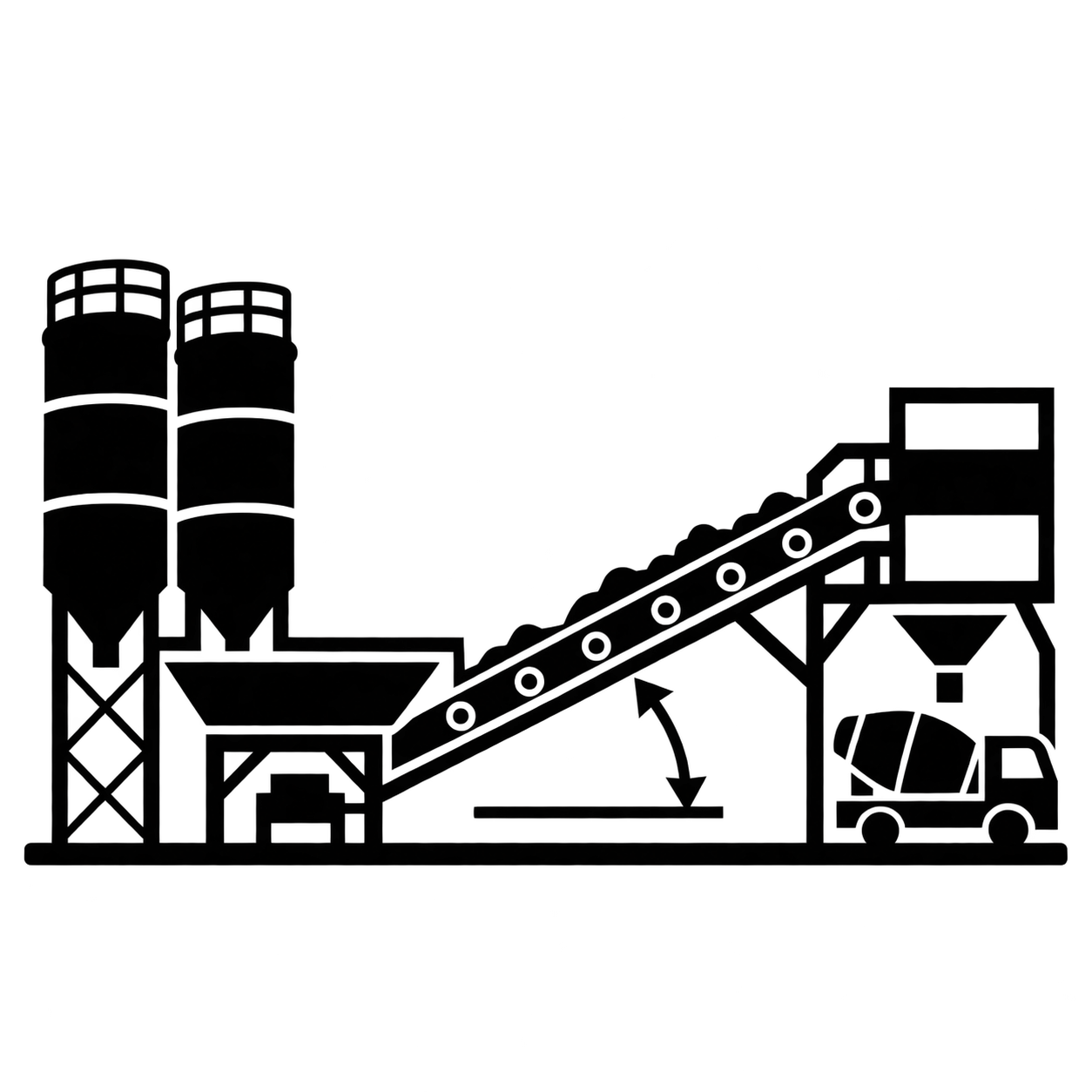
From type HN 4.0 upwards the plant is available only in the inclined belt conveyor execution, so the skip equipment is not used. An in-line silo with 4 – 8 compartments sits in front of the conveyor, aggregates are batched on a weighing belt appropriate for calibration, and the conveyor runs at 16° – 24° into an intermediate storage hopper above the mixer, from where a flap valve feeds the mixer. Compartments are charged by wheel loader or belt conveyor equipment.
Aggregate weighing system 10,000 kg, cement weighing system 2,100 kg and water weighing system 1,125 kg. The plant handles 4 – 8 types of aggregate and up to 7 types of cement. Admixture weighing for chemical additives, ice weighing for flake ice and powder weighing are available as options.
Connected load is approximately 275 kVA, with a DN 80 water connection at 3 – 4 bar operating pressure. The HN series is designed either as a stationary plant or as a semi-mobile plant without foundation, and can be supplied completely mounted or as a partially assembled unit with locally manufactured components for export.