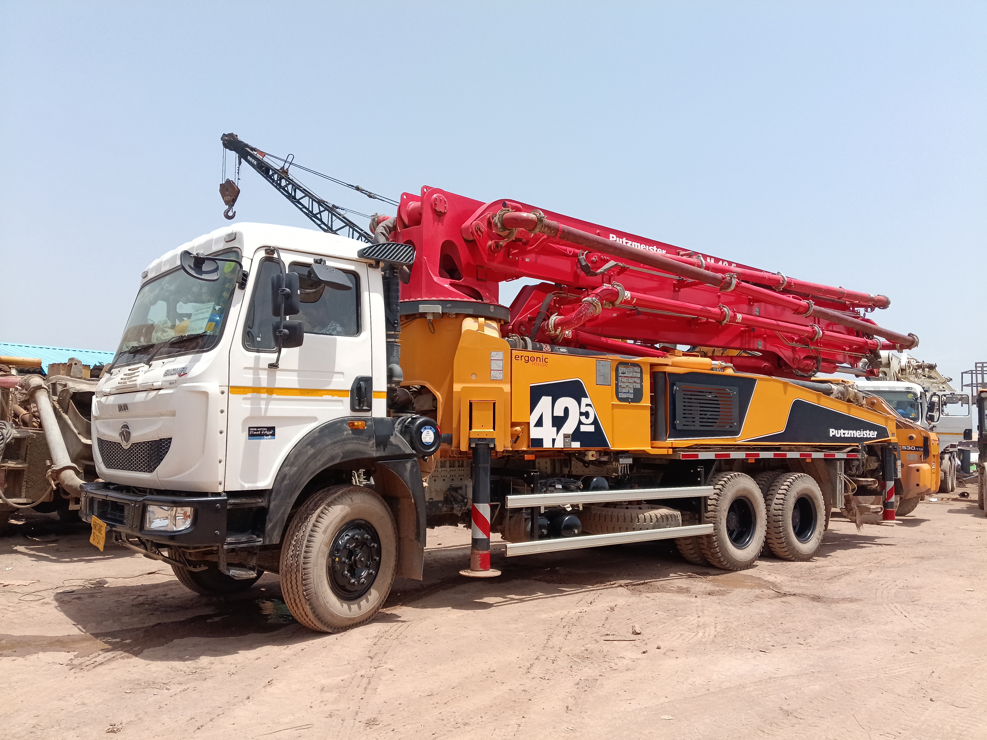
A truck-mounted concrete boom pump with a five-section 42 m M42-5 boom on Roll-and-Z folding, delivering up to 95 m³/h at 82 bar for high-rise and long-distance concrete placement. Vertical reach 41.6 m, horizontal reach 37.3 m and 31 m reach depth.
Detailed technical specifications for the Putzmeister BSF 42-5 truck-mounted concrete boom pump. Dimensions, weight and engine power depend on the truck chassis.
Daily inspections, hour-based service tasks and display-alert actions for safe, reliable concrete pumping.
Complete before every shift and after any extended shutdown.
Fold the boom, retract the outriggers and read the tank sight gauge. Check oil colour and odour.
Act if: below minimum, milky, dark or burnt-smelling. Do not pump until corrected.
Inspect the pedestal, drive cylinders, swing drive, outriggers, boom cylinders and hoses.
Act if: oil seepage, spray or pooling is found. Never search for pinhole leaks by hand.
Fill the 500 L tank and confirm the flushing pump primes and holds pressure through the hose and gun.
Act if: the tank is empty or the pump will not prime. Correct before pumping.
Check water level, piston condition and the chrome-plated delivery-cylinder bores for scoring or grout.
Act if: grey slurry appears in the water box; inspect and replace worn piston cups.
Isolate the machine and inspect the S 2318LS tube, wear ring, thrust ring and spectacle plate.
Act if: there is step wear, grout blow-by or an enlarged sealing gap.
Clean and latch the hopper grate, then lift it slightly to test the RFID agitator and pump cutout.
Act if: the agitator or pump does not stop. Remove the machine from service.
Run the agitator in both directions and inspect paddles, shaft seals and the hopper rubber collar.
Act if: the shaft binds, paddles are worn or grease escapes from a seal.
Confirm both central-lubrication systems cycle and grease all remaining points shown on the lubrication plate.
Act if: a reservoir is empty or any point, especially the slewing ring, is dry.
Inspect DN 125 pipework, bends, clamps, safety locks, end hose and retaining chain.
Act if: a pipe is thin, a clamp pin is missing or the hose is damaged.
Inspect all five boom sections, welds, pins, retainers, bearings, rails and the non-skid deck.
Act if: a crack, missing retainer or excessive pin play is found.
Cycle the front telescoping and rear swinging legs; verify locks and support-plate condition.
Act if: a leg creeps, a lock fails or a support plate is missing or damaged.
Assess bearing capacity, excavations and overhead clearance; match the Ergonic support mode to the set-up.
Act if: the ground is unstable or the displayed support mode is incorrect.
Power up the Ergonic Graphic Display and review active and stored messages before work.
Act if: an active fault appears or the display remains blank.
Test boom and pump controls on both remotes and sound the hopper-mounted horn.
Act if: either remote is unresponsive or the horn does not sound.
Test every E-stop at the remote, control cabinet and hopper; confirm pump and agitator stop.
Act if: any E-stop fails. Stop all work until repaired.
Check cooler cleanliness and confirm the electric fan operates.
Act if: the matrix is blocked or the fan does not run.
Check gearbox oil, listen during slow rotation and look for grease purge at the bearing seal.
Act if: rotation is noisy or jerky, or no grease purge is visible.
Remove loose tools and pipe; inspect rear steps, rails, grab points and the non-skid platform.
Act if: the deck is obstructed or access equipment is damaged.
Check engine oil, coolant, fuel, air pressure, tyres, wheel nuts and PTO engagement.
Act if: any chassis or PTO defect is found. Do not drive or set up until corrected.
Select an interval to view the tasks due at that stage.
Safety equipment
Function-test all safety systems and inspect electrical cabling.
Fluid and condensate
Check hydraulic-fluid level and drain accumulated condensate water.
Lines and filter indicator
Inspect for damage or leaks and check filter contamination indication.
Transfer tube and wear parts
Inspect wear and adjust the transfer-tube sealing gap.
Delivery line
Check coupling safety locks and pipe-wall thickness.
Central lubrication
Check grease level and confirm lubrication operation.
Water pump and compressor
Check oil levels; compressor tasks apply only when fitted.
Cross-pin bearings
Lubricate cardan-shaft cross-pin bearings when nipples are fitted.
After-sales inspection
Complete the first machine service with the operator present.
Transfer gearbox
Perform the first full gearbox-oil change.
Cardan cross-pin bearings
Lubricate under normal operating conditions when nipples are fitted.
Shaft and joint condition
Inspect cardan shafts, joints, guards and fasteners.
Hydraulic fluid and sump
Change fluid after condition analysis and clean the fluid sump.
Return and suction filters
Replace the vacuum return-flow filter and the suction element together.
Transfer gearbox
Change mineral transmission oil, or at least annually.
Agitator gearbox
Perform a full oil change.
High-pressure water pump
Change oil and check bolted connections.
Compressor, if fitted
Change oil, clean the intake filter and check bolted connections.
Transfer-tube bolts
Check and restore bolt tightening torque.
Cardan shafts
Inspect under normal operating conditions.
Transfer gearbox
Change synthetic transmission oil, or at least annually.
Slewing gear
Perform a full transmission-oil change, or at least annually.
Weekly
Lubricate the truck superstructure, inspect delivery-piston wear and clean the water-filter screen.
Monthly
Inspect hydraulic cylinders for leak tightness.
Water tank and boom pedestal
Check sacrificial anodes, lubricate swing-bearing teeth and follow the slewing-ring bolt retest schedule.
Boom-pedestal sealing ring
Replace after eight years.
Hydraulic filters
Replace sooner whenever the contamination indicator requires it.
Bolted connections
Check against the tightening-torque table after repair or when looseness is suspected.
Engine and transmission
Service the carrier engine and transmission at the chassis manufacturer's specified intervals.
Red requires an immediate stop or fault correction. Amber requires attention before normal operation continues.
Action: Open the HOME and Pump Status menus, identify the specific symbol or stoppage code and correct it before resuming.
Action: Clear the hopper area, close and latch the grate, and never bypass the cutout.
Action: Establish why it was pressed, make the area safe and reset it only at the activated location.
Action: Refill the water tank before flushing or washing. Do not use an override during normal operation.
Action: Refill the reservoir or repair the system before continuing operation.
Action: Repair the hopper level-control fault; automatic pump switching cannot be relied upon.
Action: Load or draw down concrete as indicated. Investigate if automatic switching behaves incorrectly.
Action: Monitor the rising level; at red, stop and replace the element immediately because the bypass opens.
Action: Arrange service and do not rely on the contamination display until repaired.
Action: Stop set-up, note the fault number and repair the monitoring system before unfolding the boom.
Action: Check the engine and speed sensor. Emergency operation disables automatic output control.
Action: Use emergency operation only when necessary and arrange sensor repair.
Action: Continue only with restricted emergency controls and repair promptly.
Action: At 85°C or above, output is limited to 20%. Allow the machine to cool, inspect cooler and fans, and do not override the reduction.
Action: Correct the displayed cause before restarting: 1 cutout, 2 E-stop, 4 pump stop, 8 engine speed, 16 lower-level sensor, 32 lubrication, 64 temperature, 128 external stop, 256 short circuit, 512 transfer-tube sensor, 1024 pressure sensor, 2048 gate valve or 4096 stroke count.
Action: Note the remaining operating hours and arrange support-system service before the limit expires.
Action: Follow the displayed additional-support procedure before unfolding or pumping.
Action: Output is automatically limited to 50%. Operate only at reduced output and arrange sensor repair.
Action: Note outlet 17, 18, 19 or 20 and arrange repair of the identified pump or transfer-tube circuit.
Action: Refill the hopper before resuming; bypass the sensor only for controlled emergency operation.
Reverse and fully depressurise the delivery line before releasing any clamp, coupling or end hose. Never bypass the hopper-grate cutout, and never unfold or slew the boom until all outriggers and the selected support mode are correct.
Everything you need to know about the Putzmeister BSF 42-5 truck-mounted concrete boom pump