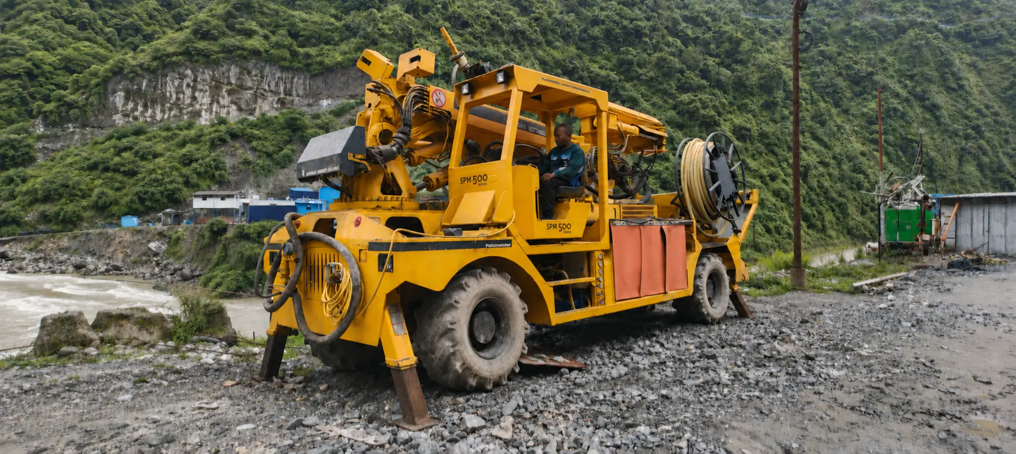
Putzmeister SPM 500 Wetkret concrete spraying equipment
PutzmeisterConcrete Spraying Equipment

Putzmeister SPM 500 Wetkret

Concrete spraying equipment for medium and large section tunnels, galleries and slopes. It combines a Putzmeister SA 17.2 telescopic spraying arm, 17 m vertical reach, 30 m³/h concrete flow, synchronized additive dosing and a compact 4WD/4WS off-road chassis with crab mode.

Vertical spraying reach
Vertical Reach17 m
Horizontal spraying reach
Horizontal Reach15 m
Concrete flow
Concrete Flow30 m³/h
Pressure
Pressure75 bar
Spraying arm
Spraying ArmSA 17.2
Diesel tank
Fuel Tank130 L

Key Highlights

Vertical spraying reach icon
Vertical Spraying Reach

17 m

Horizontal spraying reach icon
Horizontal Reach

15 m

Concrete flow icon
Concrete Flow

30 m³/h

Concrete pressure icon
Concrete Pressure

75 bar

Spraying arm icon
Spraying Arm

SA 17.2

Telescopic stroke icon
Telescopic Stroke

2 × 2.000 m

Spraying head rotation icon
Head Rotation

360°

Nozzle icon
Nozzle

DN 40 / 50

Additive range icon
Additive Range

30–700 L/h

Additive tank icon
Additive Tank

1,000 L

Fuel tank icon
Fuel Tank

130 L

Oil tank icon
Oil Tank

390 L

Water tank icon
Water Tank

200 L

Climbing capacity icon
Climbing Capacity

35% / 10%

Weight icon
Weight

15,500 / 16,000 kg

Specifications

Detailed technical specifications for the Putzmeister SPM 500 Wetkret concrete spraying equipment.

SPRAYING ARM & HEAD

  • Arm modelPutzmeister SA 17.2
  • Max. spraying reach17 m vertical / 15 m horizontal
  • Number of arm extensions2 telescopic
  • Telescopic stroke2 × 2.000 m
  • Number of arm axles9
  • Max. arm angle+60° / -23°
  • Working lights2 × LED, 24 V / 80 W
  • Spraying head rotation360°
  • Spraying head inclination±120°
  • Nutation
  • NozzleDN 40 / 50

CONCRETE PUMP & HOPPER

  • Concrete pump modelPutzmeister PM1810
  • Pump typeDouble piston
  • Pump driveHydraulic
  • Max. concrete flow30 m³/h theoretical
  • Max. concrete pressure75 bar theoretical
  • Transport cylinder diameter180 mm
  • Max. aggregate size16 mm
  • Lubrication systemAutomatic
  • Full hopper capacity350 L
  • Filling height1,440 mm
  • Hopper spotlight24 V / 70 W

ADDITIVE & POWER SYSTEM

  • Additive systemSynchronized with concrete pumping
  • Adjustment range30–700 L/h
  • Max. working pressure10.5 bar
  • Control systemPLC
  • Additive tank1,000 L
  • Diesel engine power70 kW / 100 HP
  • Diesel engine standardEU Stage IIIA
  • Pumping and spraying electric drive55 kW
  • Remote controlDual radio / cable, 15 m
  • Remote control driveElectric

OFF-ROAD VEHICLE

  • Weight without / with load15,500 / 16,000 kg
  • Turning radius inner / outer2,628 / 6,370 mm
  • Maximum climbing capacity at full load35% longitudinal / 10% transversal
  • TransmissionHydrostatic
  • Gearbox2 speed
  • Maximum speed20 km/h
  • Driving4 WD
  • SteeringHydraulic four-wheel steering (4WS), crab mode
  • Service brakesHydraulic multi-disc in oil bath for four wheels
  • Parking brakeHydraulic in oil bath for four wheels
  • Electric equipment2 batteries, 12 V / 100 Ah
  • Oil tank390 L
  • Diesel tank130 L
  • CabinFOPS / ROPS, 180° swivel seat
  • Mining wheels18”–19.5”

CABLE REEL, CLEANING & OPTIONS

  • Cable reel driveManual
  • Cable length50 m
  • Cable reel voltages400 V at 50 Hz / 440 V at 60 Hz
  • High-pressure water pump200 bar
  • Water pump flow15 L/min
  • Water pump hose15 m
  • Water tank200 L
  • Optional compressor power75 kW at 400 V / 86 kW at 440 V
  • Optional compressor air flow11 / 13 m³/min
  • Optional compressor pressure7.5 bar
  • Optional wheelsMichelin XMine D2 10.00 R15
  • Other optionsRear camera, inox water tank, 2.4 GHz radio remote, particle filter, silencer kit with catalyst
Putzmeister SPM 500 Wetkret Maintenance Checklist

Daily inspections, spraying-cycle care, hour-based service tasks and warning-alert actions for safe, reliable operation.

Daily Pre-Start Inspection

Complete before every shift and before moving the machine. Allow approximately 15–20 minutes.

Every shift
1

Engine oil

Check the dipstick with the traction engine off and the machine level.

Act if: below MIN, top up. Stop and investigate milky or foaming oil.

2

Engine coolant

Check the coolant reservoir on the engine side of the chassis.

Act if: below MIN, top up. Schedule a flush if coolant is discoloured or oily.

3

Hydraulic oil

Check the 390 L tank sight glass with the arm fully stowed and support legs down.

Act if: below range, top up with the specified grade. Do not operate with milky oil.

4

Fuel level

Check the operating-panel fuel gauge and keep the tank above one quarter.

Act if: low, refuel before the shift; do not run the tank dry.

5

Fuel water separator

Inspect the clear bowl at the base of the fuel filter.

Act if: water is visible, drain the bowl completely before starting.

6

Additive tank

Check the 1,000 L tank sight gauge and confirm the additive matches the mix design.

Act if: low, top up. Clean crystallised residue from the outlet before use.

7

Hopper, grill and agitator

Remove hardened concrete and test the electric vibrator.

Act if: material remains on the S-tube or wear plate, clean it before starting.

8

Water and cleaning system

Check the 200 L tank and briefly test the 200 bar, 15 L/min water pump.

Act if: water is low or cleaning pressure is unavailable, correct it before spraying.

9

SA 17.2 spraying arm

Inspect telescopic sections, hoses and pins; slowly cycle rotation, inclination and nutation unloaded.

Act if: hoses are worn or bulging, pins have excess play, or movement is jerky.

10

Nozzle and spray head

Confirm the DN 40/50 nozzle bore and diffuser holes are clear.

Act if: obstructed, clean before spraying to prevent pressure spikes and an uneven pattern.

11

PM 1810 concrete pump

Fill the water box with clean water and slow-test the 180 mm transport cylinders.

Act if: concrete or oil appears in the water box, inspect the relevant seals.

12

Central lubrication

Confirm the reservoir is full and the automatic system completes a cycle.

Act if: low or faulted, refill or repair before operating.

13

Remote and cable reel

Check free cable-reel winding and test radio/cable controls, including emergency stop.

Act if: any function fails or the radio link drops, do not operate until repaired.

14

Tyres and mining wheels

Check all four tyres for inflation, cuts, bulges and exposed cord.

Act if: damaged, replace before travelling and use the supplied pressure chart.

15

Batteries, lights and horn

Check both 12 V batteries, terminals, charge state, all work lights and the horn.

Act if: terminals are loose/corroded or a light or horn fails.

16

Service and parking brakes

Function-test both brake systems at low speed in a clear area.

Act if: the pedal is spongy, braking pulls, or the parking brake will not hold.

17

Cabin and seat belt

Inspect the FOPS/ROPS structure and mounting area; test the belt latch.

Act if: the structure is damaged or the belt is frayed/faulty, remove the machine from service.

18

Leaks and damage

Walk around the machine and inspect the ground, hoses and fittings.

Act if: hydraulic, fuel, water or additive is actively leaking, repair before starting.

19

Support legs

Extend, lock and retract the protected front and rear stabiliser legs.

Act if: a leg will not lock or its cylinder seeps, do not spray until repaired.

Service Schedule by Operating Hours

Select an interval to view the work due. Complete all shorter-interval tasks that are also due.

Perform before every shift and repeat cleaning work after every spraying cycle.
Engine and hydraulics

Levels and filters

Check engine oil, coolant, fuel, hydraulic oil and the fuel-water separator.

CHECK

Cooling and leaks

Keep cooling vents clear and inspect hoses, cylinders and fittings.

INSPECT
Concrete and additive path

Pump and water box

Fill the water box, test the pump slowly and clean the hopper, S-tube and wear plate.

CLEAN

Additive system

Check tank level and dosing synchronisation; flush the peristaltic pump and line after use.

CHECK
Arm and lubrication

SA 17.2 and nozzle

Cycle all spray-head movements; inspect arm sections, pins, hoses, nozzle and diffuser holes.

INSPECT

Grease systems

Confirm automatic lubrication and grease uncovered arm/support-leg points every 10 hours.

LUBRICATE
Chassis and controls

Travel systems

Test brakes, 4WS/crab mode, support legs and inspect tyres.

TEST

Electrical and safety

Test remote controls, E-stop, batteries, lights, horn, FOPS/ROPS and seat belt.

TEST

Display and PLC

Check the control-panel display for active fault or alarm codes before operation.

CHECK
Initial break-in work and recurring lubrication; confirm exact requirements in the machine Operating Instructions.
Initial fluid service

Engine oil and filter

Perform the first break-in oil and filter change when required by the engine manufacturer.

FIRST CHANGE

Hydraulic filters

Perform the initial filter change when specified for the fitted system.

FIRST CHANGE
Chassis and lubrication

Transmission and axle oils

Perform initial level checks for the hydrostatic transmission and wheel-end oil baths.

CHECK

Manual grease points

Grease arm pins/bushings, 4WS linkage and cable-reel bearing.

LUBRICATE
Inspection interval for wear, calibration, hose condition and chassis systems.
Engine and electrical drive

Air filter and belts

Inspect the air-filter element and drive-belt tension.

INSPECT

Electric drive

Visually/thermally check motor insulation and terminals; clean the cooling fan and vents.

CHECK
Pump, arm and additive system

PM 1810 wear points

Inspect transport-cylinder and piston-seal wear, the S-tube, wear plate and lubrication delivery.

INSPECT

Arm and dosing

Inspect sections, pins and spray-head play; verify lance alignment and dosing synchronisation.

VERIFY
Hydraulics and chassis

Hydraulic circuits

Inspect arm, leg and pump hoses, cylinders and fittings for cracks, bulges or seepage.

INSPECT

Brakes and steering

Inspect brake discs/oil condition, parking brake and 4WS linkage; grease as required.

SERVICE
Electrical and structure

Batteries

Load-test both batteries and inspect their terminals.

TEST

Supports and water pump

Inspect support-leg pins/cylinders and high-pressure water-pump seals and hose.

INSPECT
Complete daily, 50-hour and 250-hour work that is also due.
Engine

Oil, fuel and air filters

Change engine oil/filter, replace the fuel filter and outer air-filter element as specified by the engine maker.

CHANGE
Pump and spray equipment

Wear parts

Inspect/replace piston seals and S-tube wear parts as needed; inspect nozzle wear.

SERVICE

Peristaltic pump tube

Replace the additive-pump tube when wear requires it.

AS NEEDED
Hydraulic system

Hydraulic filters

Replace the specified hydraulic-filter elements.

REPLACE
Chassis and structure

Transmission and gearbox

Check hydrostatic-transmission and two-speed gearbox oil levels.

CHECK

Cabin and PLC

Inspect the FOPS/ROPS structure and back up/verify the control configuration.

INSPECT
Major service. Analyse hydraulic-oil condition and confirm all fluid grades and intervals before replacement.
Engine and electric drive

Engine systems

Service oil/filter, fuel filter, belts and coolant hoses to the engine manufacturer's plan.

SERVICE

55 kW electric motor

Perform an insulation test and inspect terminals and cooling.

TEST
Arm and concrete pump

Arm sections and pins

Inspect anti-stick coating and measure pin/bushing wear; replace worn parts.

INSPECT

Transport cylinders

Inspect and measure bore wear.

MEASURE
Hydraulic system

Oil and filters

Send a hydraulic-oil sample for analysis, change oil when required and replace filter elements.

ANALYSE
Transmission and axles

Driveline oils

Change hydrostatic-transmission, two-speed gearbox and axle/wheel-end oils when specified.

CHANGE
Complete all shorter-interval work and plan a detailed pump-condition assessment.
Concrete pump overhaul

Piston/cup seals

Overhaul the piston-seal system and inspect mating components for wear.

OVERHAUL

Pump wear path

Assess transport cylinders, S-tube, cutting ring and wear plate; replace by measured condition.

ASSESS
Full-machine review

Records and condition

Review service history, fault codes, oil-analysis results and structural inspections with an authorised service provider.

REVIEW
Spraying-cycle, weekly, monthly and condition-based work remains due even when operating hours are low.
Every spraying cycle

Release agent

Apply release agent on concrete-contact surfaces such as the hopper, S-tube, arm and nozzle area.

PREPARE

Prime delivery line

Prime the line with water/lubricant mixture or grout before introducing concrete.

PRIME

Additive dosing

Verify additive dosing is synchronized with pump output and matches the mix design.

VERIFY

Empty hopper safely

After spraying, reverse-pump residual concrete into the hopper, then empty it safely.

CLEAN

Flush concrete line

Flush with clean water and a foam cleaning ball, directing discharge to a safe area or ball catcher.

FLUSH

Flush additive line

Pump clean water through the additive pump and line until it runs clear.

FLUSH

Wash down and stow

Wash the arm, hopper and chassis, then stow the arm and support legs and secure the remote.

SECURE
Weekly

Lubrication and wear

Grease manual points, inspect nozzle/diffuser wear, test spray-head movement and inspect the water box and transport cylinders.

SERVICE

Remote control

Check remote-control battery and charge state.

CHECK
Monthly

Hoses and chassis

Inspect hydraulic hoses, batteries, tyre tread/sidewalls and light-oil cabin pivots.

INSPECT

Concrete and additive pumps

Inspect the S-tube, wear plate, cutting ring and additive-pump tube.

INSPECT
Storage and freezing weather

Water systems

Drain/refill the pump water box and use approved antifreeze or drain tanks and lines before freezing conditions.

PROTECT

Machine secure

Stow the arm and support legs, apply the parking brake and secure the remote.

SECURE

Lubrication & Fluids

Lubrication points, tank capacities and replacement guidance for the SPM 500 Wetkret.

Use the specified lubricant or fluid for the machine serial number. Check levels with the machine parked level, the spraying arm stowed and the support legs down.
Automatic lubrication

PM 1810 pump bearings and drive points

The centralised grease system operates continuously. Check reservoir level and confirm the cycle indicator every day.

DAILY CHECK

SA 17.2 pivots and telescopic guides

Confirm automatic delivery to covered points and manually grease any fitted points outside the system.

CONTINUOUS
Manual grease points

Support-leg pins and cylinder mounts

Lubricate with a grease gun before each spraying setup or every 10 operating hours.

10 HOURS

4WS linkage and cable-reel bearing

Grease steering knuckles and linkage weekly or every 50 hours; grease the cable-reel hub every 50 hours.

50 HOURS

Driveline joints and cabin pivots

Grease fitted propshaft universal joints every 250 hours; lightly oil hinges, seat slide and miscellaneous pivots monthly.

250 H / MONTHLY
Fuel and hydraulic oil

Diesel fuel — 130 L

Refill before each shift, keep above one-quarter tank and drain visible water from the separator before starting.

CHECK DAILY

Hydraulic oil — 390 L

Check the sight glass daily. Sample the oil and change it by condition or authorised service recommendation.

CONDITION BASED
Process fluids

Liquid additive — 1,000 L

Top up before spraying, verify the product against the mix design and flush the pump and lines after every use.

FLUSH AFTER USE

Cleaning water — 200 L

Refill before each shift. Drain or protect the water box, tank and lines whenever freezing is possible.

CHECK DAILY
Engine fluids

Engine oil

Use the traction-engine manufacturer's grade, capacity and replacement interval.

ENGINE PLAN

Engine coolant

Use the engine manufacturer's coolant specification and service schedule.

ENGINE PLAN
Transmission and axle oils

Hydrostatic drive, gearbox and axles

Confirm the correct grades, capacities and change intervals in the machine Operating Instructions or with authorised Putzmeister service.

MACHINE PLAN

After spraying

Flush additive and concrete paths, drain and refill the pump water box, then wash the arm, hopper and chassis.

CLEAN

Warning Indicators and Recommended Actions

Red requires an immediate stop or fault correction. Amber requires attention before normal operation continues.

Red — StopAmber — Check
RED

Hydraulic pressure fault

Action: Stop immediately. Do not force arm or leg movement; check oil level and the diagnostic screen.

RED

Concrete pump overload or stall

Action: Stop pumping, reverse briefly to relieve pressure, then investigate the delivery line for blockage.

AMBER

Additive dosage deviation

Action: Check additive level and pump-tube condition, then recalibrate dosing before spraying continues.

AMBER

Engine coolant temperature high

Action: Reduce load, idle the engine and check coolant level and radiator condition.

RED

Engine oil pressure low

Action: Stop the engine immediately and do not restart until the oil level and cause are checked.

AMBER

Battery or charging fault

Action: Check terminals and drive-belt condition; test the charging system before the next shift.

AMBER

Filter restriction

Action: Inspect and replace the indicated air, hydraulic or fuel filter before full restriction.

Frequently Asked Questions

Everything you need to know about the Putzmeister SPM 500 Wetkret

The SPM 500 Wetkret provides 17 m vertical spraying reach and 15 m horizontal spraying reach using the Putzmeister SA 17.2 telescopic spraying arm.

It uses a Putzmeister PM1810 double-piston pump with theoretical concrete flow up to 30 m³/h and concrete pressure up to 75 bar.

It is suitable for medium and large section tunnels, galleries and slopes, with concrete spraying technology designed for underground and difficult site conditions.

The off-road chassis has 4WD, hydraulic four-wheel steering with crab mode, 20 km/h maximum speed, 130 L diesel tank, 390 L oil tank, 1,000 L additive tank and 200 L water tank.