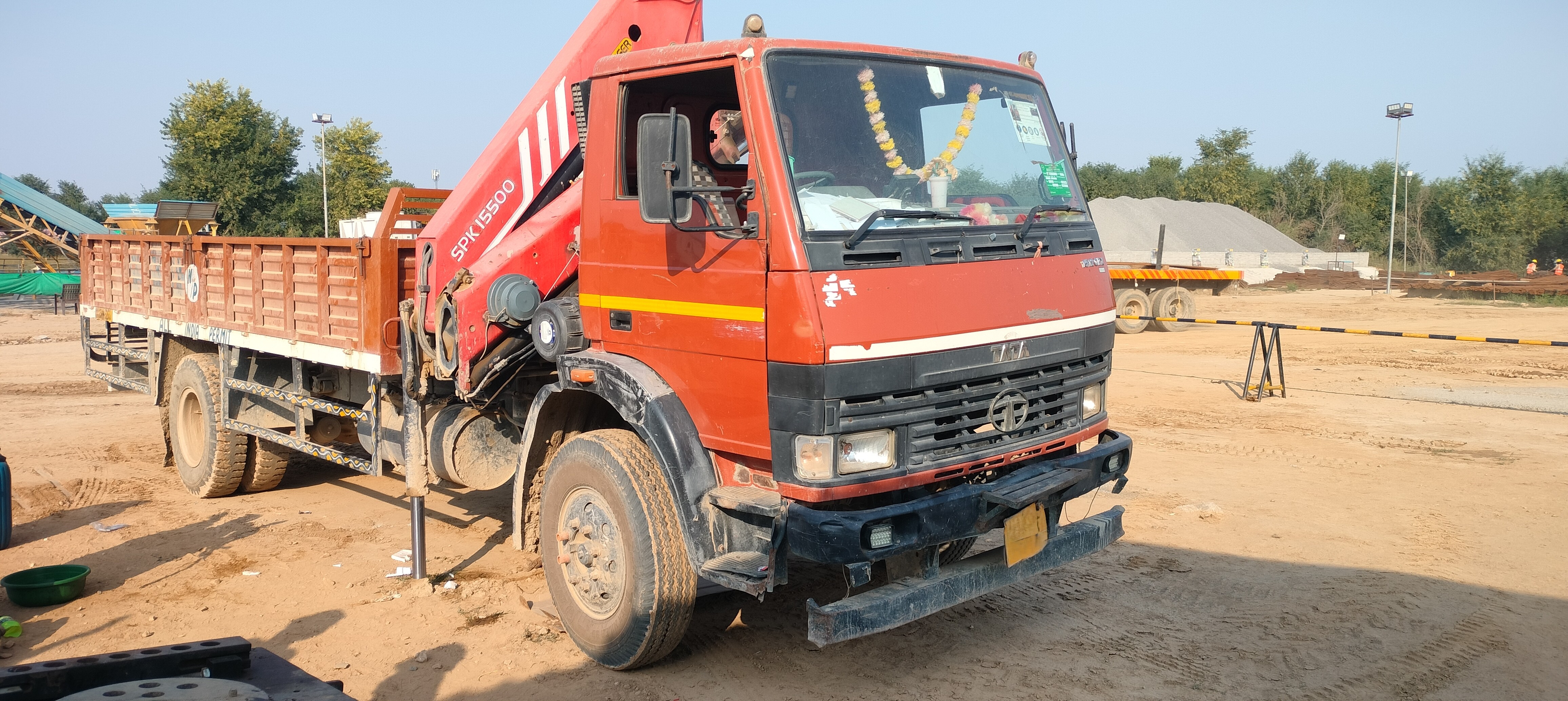
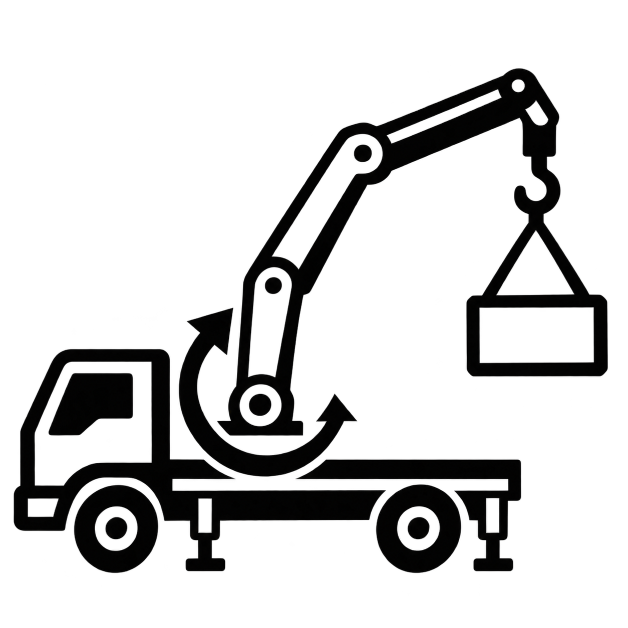
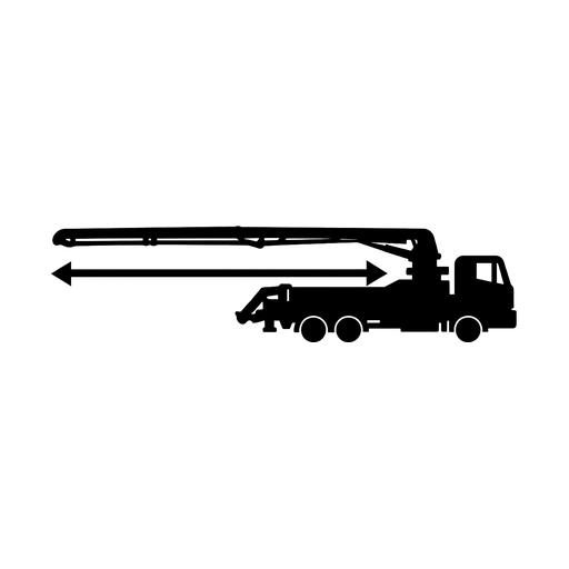
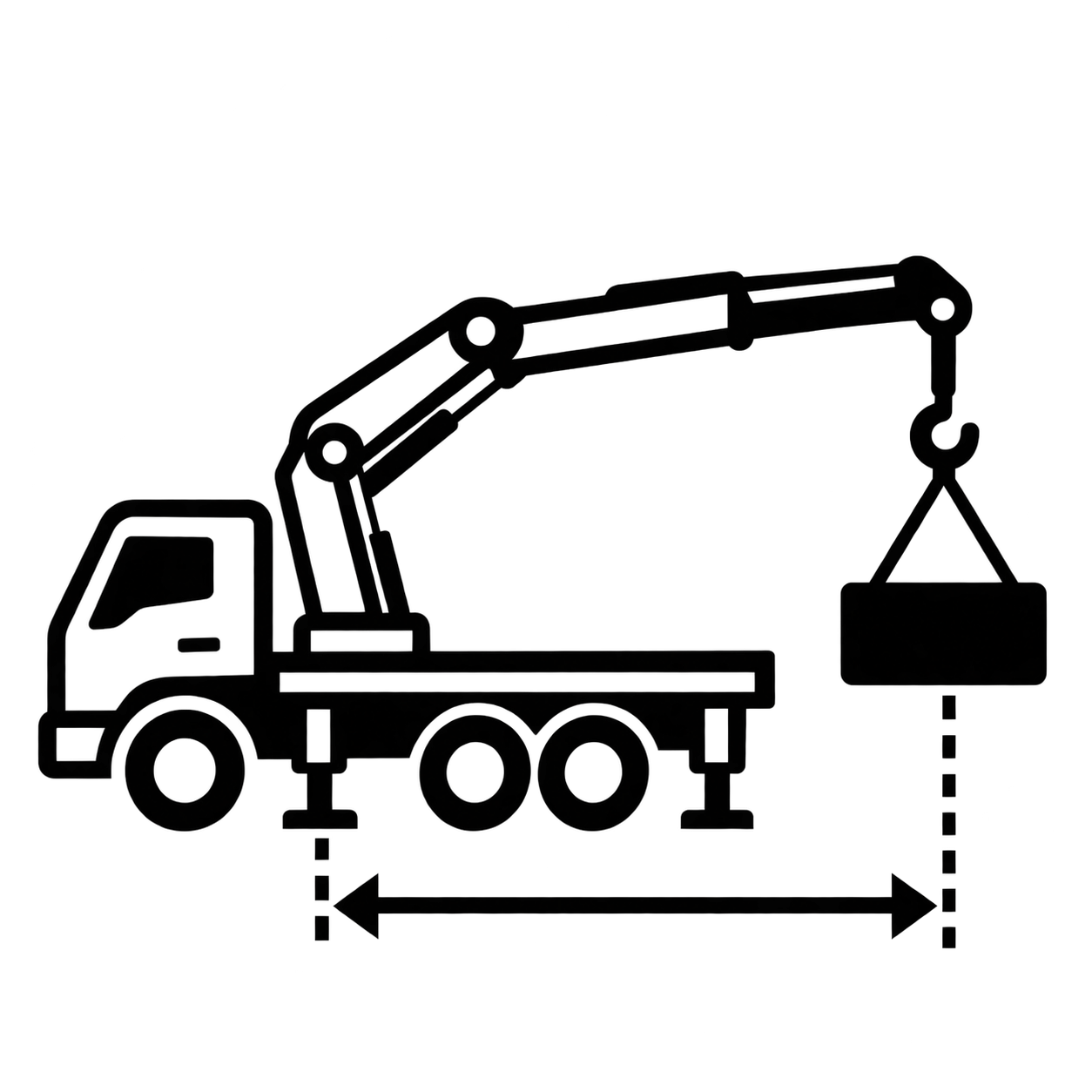
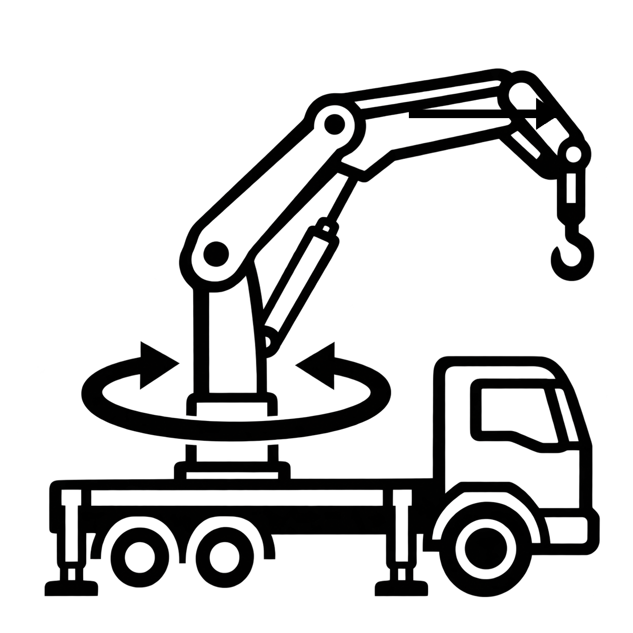
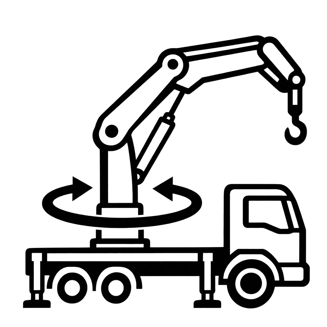
A knuckle boom loader crane rated at 14.6 mt lifting moment and 6,200 kg maximum capacity, with up to 14.5 m hydraulic outreach on the five-extension version and 420° slewing. Hexagonal high-tensile boom design with load holding valves fitted as standard on all cylinders. Overload protection and radio remote control are available as options. Built to EN 12999 as a lifting solution for 2-axle truck chassis.
Lifting Moment14.6 mt
Capacity6,200 kg
Max OutreachUp to 14.5 m
Slewing420°
Pressure300 bar
Dead Weight1,619 kg
Key Highlights
Lifting Moment
14.6 mt
Lifting Capacity
6,200 kg
Max Outreach
Up to 14.5 m (D)
Capacity at Reach
650 kg
Extension Booms
5 (D)
Slewing Angle
420°
Slewing Moment
1.8 mt
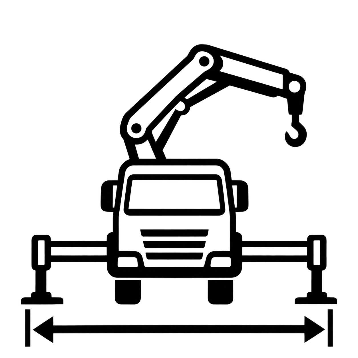
Stabilizer Spread
5,600 mm
Operating Pressure
300 bar
Pump Capacity
40–60 l/min
Fitting Space
810 mm
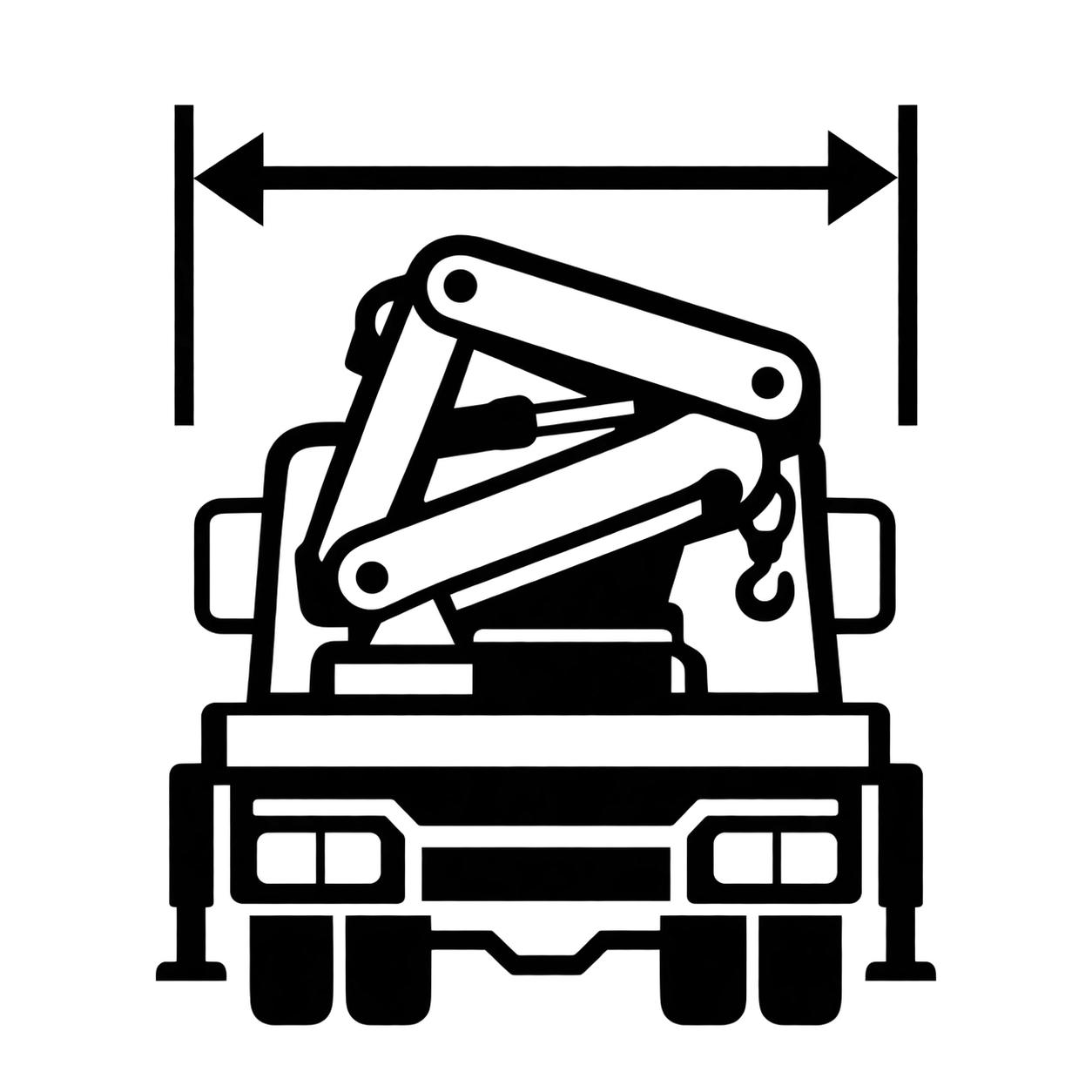
Width Folded
2,500 mm
Dead Weight
1,619 kg
Carrier
2-Axle Truck
Standard
EN 12999
Specifications
Detailed technical specifications for the Palfinger SPK 15500 Knuckle Boom Crane
Daily pre-start checks · hour-based service schedule · warning actions · fluids and specifications.
Before Start
Truck on firm level ground, parking brake on, crane folded in transport position, PTO off.
Before the first lift
1
Overhead power lines
Look for lines anywhere in the full slewing range of the crane and the load. Keep 1 m up to 1,000 V, and 5 m if the voltage is unknown or above 1,000 V.
Act if: a line is closer than these distances. Do not set up until the line operator has switched it off.
2
Wind and temperature
Check wind speed and shade temperature at the site. No wind or temperature sensor is fitted to the crane.
Act if: wind is 50 km/h or more (34 km/h with bulky loads or a near-vertical boom), or ambient is above +50 °C. Do not operate.
3
Ground under the supports
Check for soft fill, cavities, manhole covers, buried pipes, trench and slope edges. Support pads can press up to 400 N/cm², while asphalt carries about 20 N/cm².
Act if: the ground is soft or hollow below. Use larger pads or move the truck. Never support on an edge or a cover.
4
Crane structure, pins and bolts
Walk round the base, column, booms and cylinders. Look for cracks at welds and bending edges, bends and heavy rust. Check every pin has its locking device and no bolts are loose.
Act if: any crack or bend is found — do not operate. A missing pin lock or loose bolt must be fixed before work.
5
Hydraulic leaks
Look for wet oil, drips under the crane, cut, rubbed or swollen hoses, cracked pipes, loose fittings and missing hose sleeves.
Act if: there is any leak or damaged hose. Do not operate: oil at 300 bar can pierce skin and hot oil can scald.
6
Lubrication
Check the slewing rack, column bearing, pin bushings and stabilizer pivots are not dry, and that the outrigger slide surfaces are clean.
Act if: points are dry or creaking. Lubricate before work — lack of lubrication is a stop condition.
7
Outrigger beams and stabilizer cylinders
Check the beam locks and safety catches work, the latch levers of tiltable stabilizer cylinders lock, and the support pads are on the truck.
Act if: a lock or latch does not engage. Do not use that support.
8
Hook and safety latch
Check the spring latch closes by itself and the 8 t hook has no cracks, nicks or bending. The hook pin must be secured.
Act if: the latch does not close or the hook is damaged. Take the hook out of service.
9
Load chart, labels and stands
Check the load capacity label at each control station and all warning labels are readable. Stands, steps and the top seat must be free of oil, grease and mud.
Act if: the load chart is missing or unreadable — do not lift until it is replaced. Clean any slippery stand before use.
10
Optional equipment
Remote control: handset and spare battery charged and the handset undamaged. Hose trays: hoses lying correctly. Quick couplings: clean and capped.
Act if: the handset is damaged — work from the manual control station. Free any hose jammed in a tray before extending the booms.
After Start
PTO engaged, no load on the hook, all extension booms retracted.
No load
11
Supports and levelling
Extend the outrigger beams fully until the end mark is visible. Lower the stabilizers to firm ground contact without lifting the truck. Level the truck until the bubble sits in the inner circle; tilt must not exceed 1° in any direction.
Act if: the bubble is outside the inner circle — re-level before unfolding. Never lift the truck off its wheels.
12
Operating levers and emergency cut-off
Check each lever moves freely and springs back to neutral. Run any function and press the emergency cut-off: the crane must stop and no other function may move. Release it and all functions must work again.
Act if: a lever is stiff or does not return to neutral, or the crane does not stop. Do not operate.
13
Overload protection test
Only where overload protection is fitted. Raise the main boom fully at medium speed. A lever-lock device must block the movements that increase load moment; an electronic device must show a simulated overload.
Act if: movements are not blocked or no overload is shown — the protection has failed. Do not operate. Skip this check on a crane without overload protection.
14
All movements, noises and hour counter
Run each function slowly through its full range without load. Watch the speed and listen for noise. Note the hour counter reading and check for the service symbol.
Act if: there is abnormal noise, or jerky, unusually fast or unusually slow movement. Stop work.
Service Schedule by Hours
Select an interval. The hour counter counts crane hours, not truck running hours.
Reading the schedule: at about 4 crane hours a day the 50-hour point comes round every 12–13 working days. Intervals depend on application, duty cycle and environment — hot, dusty and long-running site work may need shorter intervals. The truck engine, gearbox, PTO and chassis follow the truck manufacturer's own schedule and are not covered here.
Done one time only, after the first 50 operating hours. Carried out by a service partner and logged in the machine maintenance record.
Hydraulic system
Filters
High-pressure, return and tank air filter elements.
REPLACE
Hydraulic oil level
Check with supports retracted and the crane in transport position.
CHECK
Lines, hoses, screw joints
Inspect for cuts, rubbing and cracks, then tighten.
INSPECT
Base and slewing
Crane base mounting bolts
Flange bolts to 450 Nm with a torque wrench.
TIGHTEN
Slewing cylinder
Check and tighten the fixings.
TIGHTEN
Work in this order: clean, then inspect, then lubricate. May be done by the operating company or the operator. Switch off hydraulic and electric power first.
General
Cleaning
pH-neutral cleaner; water no hotter than 60 °C. Never aim the jet at electrics, plastic parts, bearings or labels.
CLEAN
Whole crane and attached parts
Find the cause of any damage. Replace missing or worn parts at once.
INSPECT
Labels and load capacity labels
Replace anything missing or unreadable at once.
CHECK
Base and slewing
Crane column bearing
Grease at all nipples in 60° steps across the slew range.
GREASE
Slewing rack
Press in grease, slew a full turn, then repeat twice. Grease is not visible on the rack.
GREASE
Boom system
Steel parts
Welds and bending edges. A crack or bend means the crane is taken out of use.
INSPECT
Pin bushings
Remove old dirty grease first and move the part while greasing.
GREASE
Extension booms and slide rails
Never grease. Use dry PTFE spray only if the booms chatter or creak.
CLEAN
Pins, locking devices, bolts
Tighten loose bolts to the listed torque. Replace bent pins.
CHECK
Load holding valves
Confirm the seals are present and unbroken.
INSPECT
Hydraulic system
Hydraulic oil level
Supports retracted, crane in transport position. Also check after any leak.
CHECK
Lines, hoses, screw joints
Cuts, rubbing, cracks, porous or swollen hoses.
INSPECT
Hose and cable protection sleeves
Check present and undamaged.
INSPECT
Stabilizers
Outrigger beam slide surfaces
Dry PTFE spray, never grease.
SPRAY
Outrigger interlock
Dry PTFE spray; confirm the locks engage.
SPRAY
Tiltable stabilizer pivot and cam lock
Grease the pivot and check the latch.
GREASE
Controls and hook
Operating levers and control rods
Dry PTFE spray; confirm return to neutral.
SPRAY
Electrical parts
Cables, sockets, switches, sensors and display for cuts, rubbing and looseness.
INSPECT
Hook and safety latch
Cracks, deformation and wear, then spray.
INSPECT
Whichever comes first. Carried out by a service partner and logged in the machine maintenance record. 1,000 is a multiple of 50, so the 50-hour work is also due at this service.
General
Cleaning before service
pH-neutral cleaner; water no hotter than 60 °C.
CLEAN
Whole crane and attached parts
Full visual inspection.
INSPECT
Base and slewing
Crane base mounting bolts
Inspect, then tighten to 450 Nm.
TIGHTEN
Slewing cylinder
Inspect and tighten.
TIGHTEN
Crane column bearing
Grease, and have the bearing clearance inspected.
GREASE
Slewing rack
Press in grease, slew a full turn, repeat twice.
GREASE
Boom system
Steel parts
Welds and bending edges.
INSPECT
Pin bushings
Remove old grease, then regrease.
GREASE
Extension booms and slide rails
Clean only; never grease.
CLEAN
Hydraulic system
Hydraulic oil
Full oil change. Yearly oil maintenance can lengthen this interval.
CHANGE
Filters
High-pressure, return and tank air filter elements.
REPLACE
Lines, hoses, screw joints
Inspect and tighten.
INSPECT
Protection sleeves
Replace if damaged or missing.
REPLACE
Pump performance
Check delivery and speed.
CHECK
Controls and safety
All control equipment
Including every emergency cut-off button. Recheck all safety systems after any maintenance or repair.
CHECK
Overload protection
Where fitted. Only a service partner may set or adjust safety equipment.
CHECK
Operating levers and control rods
Spray, then check the function.
SPRAY
Radio remote control
Where fitted — check the function.
CHECK
Central lubrication
Where fitted — check the function.
CHECK
Ancillary equipment
Where fitted — follow the attachment's own instructions.
CHECK
Hook and lifting gear
Lifting gear
Grease the lifting gear.
GREASE
Time-based items that do not follow the hour counter.
Time-based replacement
Hydraulic hoses (all)
Replace every 6 years, and sooner if damaged.
6 YEARS
Hook and shackle
Hook and shackle inspection
By a service partner, at least every 12 months. Out of service if the mouth opening has grown more than 10% or the thickness has worn more than 10%.
12 MONTHS
Fluids, Lubricants & Specifications
Use clean filling equipment and the correct grade for ambient conditions.
Hydraulic oil
Oil type
Synthetic ester (biodegradable) or mineral oil. Never mix different oils.
SPEC
Viscosity
Not thinner than 10 cSt at the highest working temperature, not thicker than 1,000 cSt at cold start.
SPEC
Temperature
Working range −30 to +80 °C; ideal +30 to +60 °C. Read after crane use.
30–60 °C
Cleanliness
Purity class 15/12 to ISO 4406.
ISO 4406
Oil tank
Tank capacity.
80 L
Grease and spray
Grease
NLGI 2, code KP2K-35. Dropping point 150 °C, worked penetration 265/295, base oil above 80 mm²/s at 40 °C, water resistance 0/90. Free of solids; no graphite grease.
NLGI 2
Dry PTFE spray
For the operating levers, outrigger slide surfaces, interlock, extension booms and hook. Never grease these points.
Mouth opening grown more than 10%, or thickness worn more than 10% of nominal.
10%
Support pad pressure
Up to 400 N/cm² under the jacks. Size the pads to the ground — asphalt and coarse sand about 20 N/cm², stabilized crushed stone about 25 N/cm².
400 N/cm²
Vehicle inclination
Level bubble in the inner circle.
MAX 1°
Operating limits
No operation at wind 50 km/h or more (34 km/h with bulky loads), below −30 °C or above +50 °C ambient.
LIMITS
Electrical and controls
Emergency cut-off
Stops all crane functions. One button at every control station and on the remote handset.
0.5 s
Operating hours counter
Service interval counted down from 1,000 h. The wrench symbol flashes ten times at switch-on when less than 50 h remain, and continuously when overdue.
1,000 h
Power line distances
1 m up to 1,000 V; 5 m where unknown or above 1,000 V. After contact with a live line, stay on the truck and keep others 10 m away.
1 m / 5 m
Cleaning and storage
Cleaning
Crane switched off. pH-neutral, skin-friendly cleaners only, washed in a bay with an oil separator. High-pressure water no hotter than 60 °C, nozzle kept at a distance, never aimed at electrics, plastic parts, bearings or labels. No abrasive rags or brushes.
MAX 60 °C
Note: this checklist is a site quick-reference aid for trained operators. The documentation supplied with the crane and the truck remains the governing authority. Statutory lifting-equipment inspection and certification rules take precedence over anything stated here.
Warning Actions
RED — stop immediately. AMBER — act before continuing.
Where warnings show: the standard crane has no warning screen and no sensors for leaks, cracks, oil temperature, wind or power lines. Most warnings are found through the operator's visual checks, unusual noise and lever response. The indicators fitted are the digital hour counter, the oil level gauge on the tank and the level bubble at each support control station. An overload device, an electronic display and a radio remote are options — never assume a protection that is not fitted to your crane.
RED
Safety system fails the daily test
Action: The emergency cut-off does not stop the crane, or the overload device does not block an overload. Do not operate; call the service partner. Ignored: no way to stop the crane in an emergency, and it can be overloaded without warning.
RED
Hydraulic leak, burst hose or oil spray
Action: A hose, pipe, fitting or seal has failed under pressure. Stop all movement, land the load without increasing outreach, switch off the PTO and keep people clear of the spray. Ignored: injection injury, burns, fire and loss of load holding.
RED
Load or boom creeps down with levers in neutral
Action: A load holding valve or cylinder seal is leaking; the limit is 0.2% of outreach per minute. Land the load, stop work and call the service partner. Ignored: the load drops with nobody operating the crane.
RED
Crack, bend or deformation
Action: Found in a boom, the column, the base, an outrigger or a weld, caused by overload, side pull or fatigue. Land the load, fold the crane only if it is safe, and take it out of service. Ignored: sudden boom or support failure.
RED
Support sinks, outrigger unlocks or truck tilts over 1°
Action: The ground is giving way or a support is not locked. Stop, reduce outreach, land the load and re-support on firm ground with larger pads. Ignored: the truck tips over.
RED
Boom or load near a power line
Action: Inside 1 m up to 1,000 V, or 5 m where the voltage is unknown or above 1,000 V. Stop and move away the way you came. On contact, stay on the truck, keep others 10 m away and have the line switched off. Ignored: fatal electric shock.
RED
Strong wind or extreme heat
Action: Wind 50 km/h or more (34 km/h with bulky loads or a near-vertical boom), or ambient above +50 °C. Land the load and fold the crane. Ignored: the load swings out of control and the boom and supports are overloaded.
RED
Hook latch does not close, or hook cracked or opened up
Action: The latch spring is broken, or the hook is worn or bent beyond 10%. Do not lift; take the hook out of service and replace it. Ignored: the sling slips off the hook and the load falls.
RED
Lever stiff, not returning to neutral, or crane moves on its own
Action: A control valve or lever linkage fault. Press the emergency cut-off and do not operate; call the service partner. Ignored: uncontrolled crane movement, crushing and collision.
AMBER
Overload limit reached
Action: Movements that increase load moment are blocked. Reduce the load moment by retracting the extension booms or reducing outreach. Use an overload bypass only to move out of overload, never to add load. Ignored: boom and supports overloaded and the truck can tip.
AMBER
Crane stops — electrical or electronic fault
Action: The crane does not respond to the levers. Return the levers to neutral, reset any electronic display and check the fuse. If it does not clear, put the crane in transport position using the emergency by-pass, which switches the safety systems off, then call the service partner.
AMBER
Remote control does not work
Action: Where fitted: a flat battery, a link fault or a handset fault. Fit the charged spare battery, then try the cable connection, then switch to manual and finish from the control station. Ignored: the operator works without full view of the load.
AMBER
Hydraulic oil hotter than the ideal range
Action: Oil read after work is outside the ideal 30–60 °C band, and must never exceed 80 °C. Call the service partner if it repeats. Ignored: faster wear of seals, hoses and pump, and the oil breaks down.
AMBER
Creaking, chattering, dry points or trapped hose
Action: Unusual noise or a visible fault during operation. Stop the movement, lubricate or free the hose. If a grease nipple will not take grease, replace it. Ignored: bearing, pin and pump wear, seized slewing and hose damage.
AMBER
Service due or overdue
Action: The hour counter wrench symbol flashes ten times at switch-on when less than 50 hours remain, and flashes continuously once the service is overdue. Book the service. Ignored: missed filter and oil changes.
Frequently Asked Questions
Everything you need to know about the Palfinger SPK 15500 Knuckle Boom Crane
The Palfinger SPK 15500 has a maximum lifting capacity of 6,200 kg and a maximum lifting moment of 14.6 mt. At its full hydraulic outreach of 14.5 m it still lifts 650 kg.
The SPK 15500 reaches a maximum hydraulic outreach of 14.5 m with up to 5 extension booms (D version). Shorter boom packages are available at 6.2 m standard, 8.1 m (A), 10.3 m (B) and 12.4 m (C).
Palfinger specifies the SPK 15500 as a lifting solution for 2-axle trucks. The carrier must provide 810 mm of clear fitting space on the chassis frame and a hydraulic supply of 40–60 l/min at 300 bar from the truck PTO. Allow 5,600 mm of width for stabilizer deployment and 1,619 kg of payload for the crane itself. The exact chassis is configured to order.
No. The SPK 15500 is a knuckle boom loader crane driven entirely by the carrier truck's PTO-fed hydraulic system at 40–60 l/min and up to 300 bar. It has no independent engine, which keeps the crane's dead weight at 1,619 kg.
Load holding valves are fitted as standard on all cylinders, together with a high pressure filter. Overload protection is not part of the standard crane: a hydraulic lever-lock or an electronic overload device can be specified as an option, as can radio remote control for operation outside the danger zone. The crane is built to the European standard EN 12999.