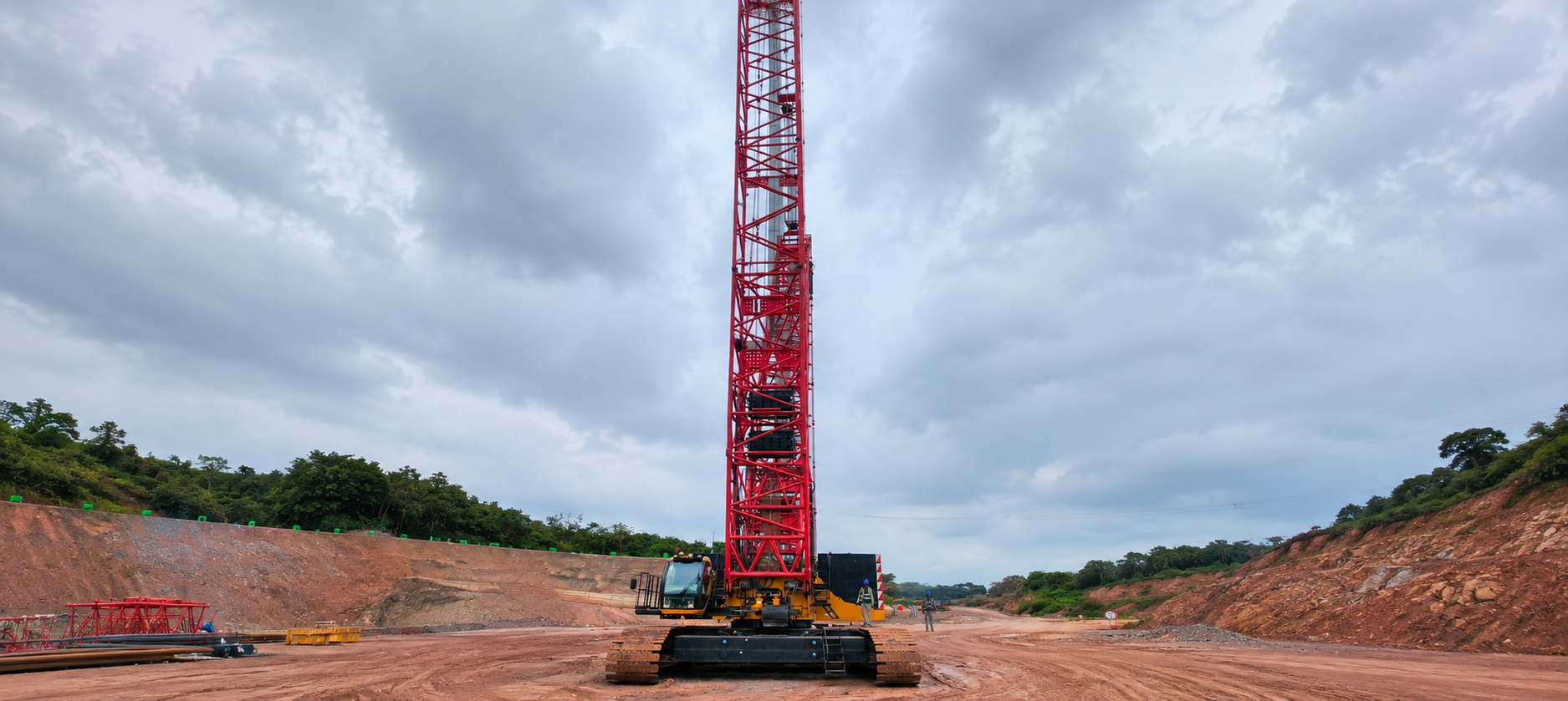
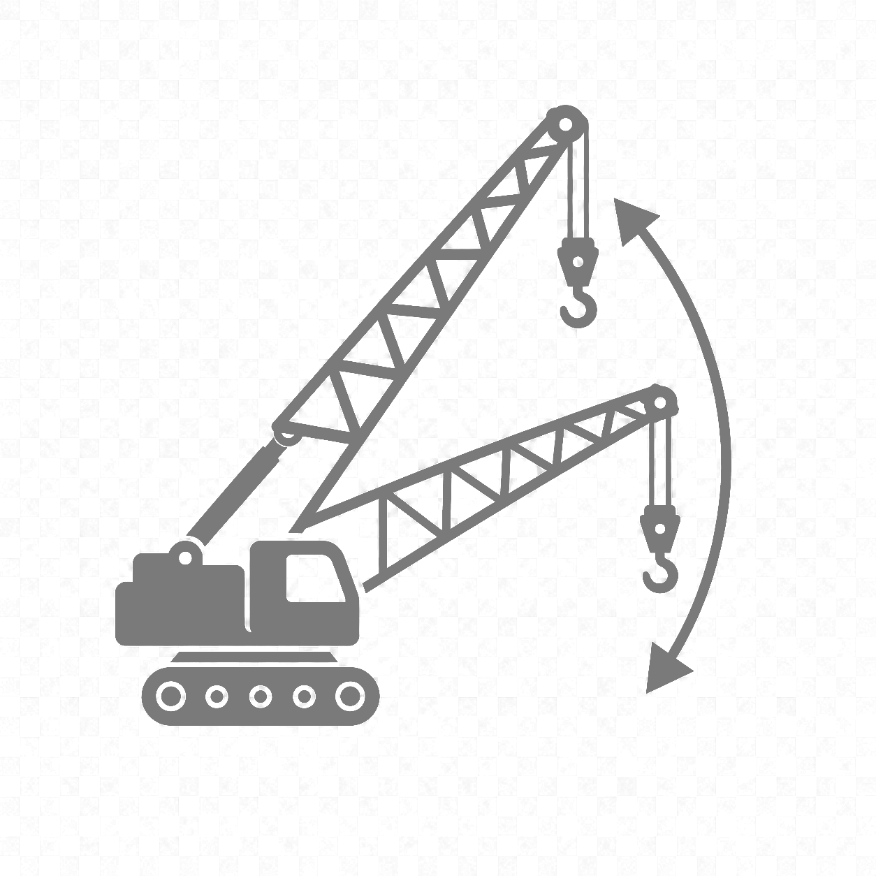
The SANY SCC4000A-2 is a 400-tonne crawler crane with 2,400 t.m standard lifting moment and 5,280 t.m superlift lifting moment. It features a 24-84 m main boom, 84 m + 84 m longest boom+jib, Cummins QSM11 298 kW Euro Tier III engine, Porsche-designed cab, CAN-bus load moment limiter and about 340 t operating weight.
Capacity400T
Max Boom84m
Lift Moment5280 t·m
LJDB Jib24–84m
Engine298 kW
Fuel Tank1165 L
Key Highlights
Max Lift Capacity
400 t
Superlift Moment
5,280 t.m
Standard Moment
2,400 t.m
Main Boom
24 - 84 m
Longest Boom + Jib
84 m + 84 m
Engine
Cummins QSM11, 298 kW
Max Torque
1,898 N.m @ 1,400 rpm
Travel Speed
0-1.0 / 0-0.4 km/h
Operating Weight
about 340 t
Ground Pressure
0.167 MPa
Hook Options
400 / 260 / 160 / 50 / 16 t
Gradeability
15%
Luffing Jib
24 - 72 m
Max Transport Weight
44.9 t
Safety System
CAN-bus LMI
Specifications
Detailed technical specifications for SANY SCC4000A-2 400T Crawler Crane
Act if: visibility is restricted or a control, warning device or wind reading is unreliable.
12
Ground, mats & lubrication
Verify level mats and adequate ground support, then grease specified pins, bearings and pivots.
Act if: settlement, soft ground, damaged mats or dry lubrication points are found.
Service Schedule by Hours
Select an interval to view the main work due; include earlier recurring checks.
Complete before every shift or at approximately 10 operating hours.
Engine & fluids
Oil, coolant and hydraulic oil
Check levels, condition and visible leakage.
CHECK
Fuel-water separator
Drain collected water and sediment.
DRAIN
Lifting & safety
Ropes, tracks and indicators
Inspect ropes, air restriction, track tension, display and wind gauge.
INSPECT
Safety systems & pivots
Test LMI/LML and anti-two-block; grease specified pivots.
SERVICE
Also complete all daily checks.
Undercarriage & drive
Reducers, tracks and sheaves
Inspect reducer oil, track pads, sheaves and rope guards.
INSPECT
Hydraulic system
Check lines, fittings and components for leaks.
CHECK
Structure & lubrication
Boom, jib and counterweight pins
Inspect pins, clips, bolts and retainers.
INSPECT
Slewing gear and connection pins
Lubricate gear teeth and specified boom/jib pins.
GREASE
Includes daily and 50-hour work; shorten intervals for severe-duty operation.
Engine & intake
Engine oil and filter
Change when required for severe-duty conditions.
CHANGE
Outer air-filter element
Clean or replace according to restriction and condition.
CLEAN
Systems inspection
Boost, slew, travel and electrical
Check components, connections and operating condition.
CHECK
Wire ropes and safety devices
Continue detailed inspection and functional testing.
INSPECT
Includes all work due at the shorter intervals.
Filters & engine
Fuel and hydraulic filters
Change fuel, return and pilot filters.
REPLACE
Belts, turbo, hoses and clamps
Inspect for wear, damage, looseness and leakage.
INSPECT
Drive & electrical
Reducer oil
Perform the initial travel, slew and winch reducer oil change where applicable.
CHANGE
Battery and slewing ring bolts
Check terminals, charging condition and bolt security.
CHECK
Major service including all preceding inspections and lubrication tasks.
Fluids & filters
Engine oil and fuel filters
Change engine oil/filter and both scheduled fuel filters.
CHANGE
Hydraulic filters and oil
Replace filter media; sample or change oil according to condition.
SERVICE
Diagnostics & safety
Control-system diagnostics
Scan operating systems and resolve stored faults.
TEST
Safety-device function
Complete comprehensive alarm, limiter and cut-out checks.
VERIFY
Full major service and crane-condition review, including all shorter-interval work.
Engine & cooling
Oil, fuel and safety air filter
Change scheduled engine fluids and filter elements.
REPLACE
Coolant system
Replace the coolant filter and flush the system when scheduled.
SERVICE
Crane condition
Reducers, winches, brakes and tracks
Change reducer oils and conduct a detailed mechanical inspection.
OVERHAUL
Structure and systems
Inspect structural connections and complete full diagnostics.
REVIEW
Warning Actions
Stop safely and correct the cause before returning the crane to service.
RED
Engine oil pressure
Action: stop the engine immediately. Check the oil level, filter, cooler and turbo oil lines; do not restart until correct pressure is verified.
RED
LMI/LML overload
Action: stop lifting, do not override the system, and lower the load by controlled descent. Verify the load chart and crane configuration.
RED
Anti-two-block
Action: stop hoisting immediately, lower the hook block safely, and inspect the switch, rope and boom-tip sheaves.
RED
Wire-rope damage
Action: stop all operations for broken wires, kinks, birdcaging, corrosion or diameter loss; remove a rejected rope from service.
AMBER
Hydraulic oil temperature
Action: stop lifting, stabilise the load, idle without hydraulic movement, and check oil level, filters and cooler cleanliness.
AMBER
High wind speed
Action: reduce radius, lower the load, and stop lifting when wind reaches the limit for the fitted crane configuration.
AMBER
Slewing anomaly
Action: stop slewing and inspect reducer oil, ring bolts, gear teeth, lubrication and bearing condition.
AMBER
Low fuel
Action: refuel before continuing. Do not run the Cummins QSM11 dry, because air entry can require professional fuel-system bleeding.
AMBER
Hydraulic filter indicator
Action: lower the load first, then replace the clogged return or pilot filter at the next safe opportunity before heavy lifting continues.
AMBER
Ground or track issue
Action: stop lifting, re-level the crane, improve mat support, or repair loose or damaged undercarriage components.
Critical rule: overload, anti-two-block, wire-rope failure, oil-pressure loss or uncontrolled movement requires full stop. Do not continue work by bypassing safety devices.
Fluids, Lubricants & Capacities
Use the specified grade and keep filling and lubrication equipment clean.
Fuel & engine
Fuel tank
Clean ULSD suitable for the Tier III engine; drain the water separator daily.
1165 L
Engine oil
SAE 15W-40 heavy-duty diesel oil suitable for the Cummins QSM11.
34–39 L
Coolant
Heavy-duty antifreeze coolant with the correct additive concentration.
SYSTEM FILL
Hydraulic system
Hydraulic tank
ISO VG 46 anti-wear hydraulic oil for normal conditions; select viscosity for ambient temperature.
817 L
Oil condition
Keep transfer equipment clean and investigate milky, dark or contaminated oil before operation.
CHECK
Reducers & drives
Slewing reducer
Use heavy-duty EP gear oil suitable for a high-load planetary reducer.
PER REDUCER
Travel and winch reducers
Use the specified EP gear oil and maintain each reducer at the correct level.
PER REDUCER
Grease & rope care
Pins, bearings and slewing points
NLGI No. 2 EP grease for boom/jib connections, pivots and heavy-duty bearings.
AS REQUIRED
Wire ropes
Apply a compatible wire-rope dressing evenly to the 26 mm ropes.
AS REQUIRED
Before servicing: park on firm level ground, secure suspended components, isolate the crane, release stored hydraulic pressure and allow hot systems to cool.
Frequently Asked Questions
Everything you need to know about the SANY SCC4000A-2 crawler crane
The SCC4000A-2 has a maximum rated lifting capacity of 400 t. Its maximum rated lifting moment is 2,400 t.m, or 5,280 t.m with the superlift device.
The SCC4000A-2 offers a 24-84 m main boom, 24-72 m luffing jib, 24-84 m luffing jib with superlift, and a longest boom + jib combination of 84 m + 84 m.
The crane uses a Cummins QSM11 Euro Tier III engine rated at 298 kW @ 1,800 rpm, with maximum output torque of 1,898 N.m @ 1,400 rpm.
Travel speed is 0-1.0 km/h in high range and 0-0.4 km/h in low range. Gradeability with base boom and cab backwards is 15%.
The SCC4000A-2 includes SANY CAN-bus load moment limiter, over-hoist protection, over-release protection, boom and jib angle limits, back-stop device, CCTV monitoring, fault auto-diagnosis, black box, anemometer, electronic level indicator, hook latch, swing/travel alarm, seat interlock and emergency stop.