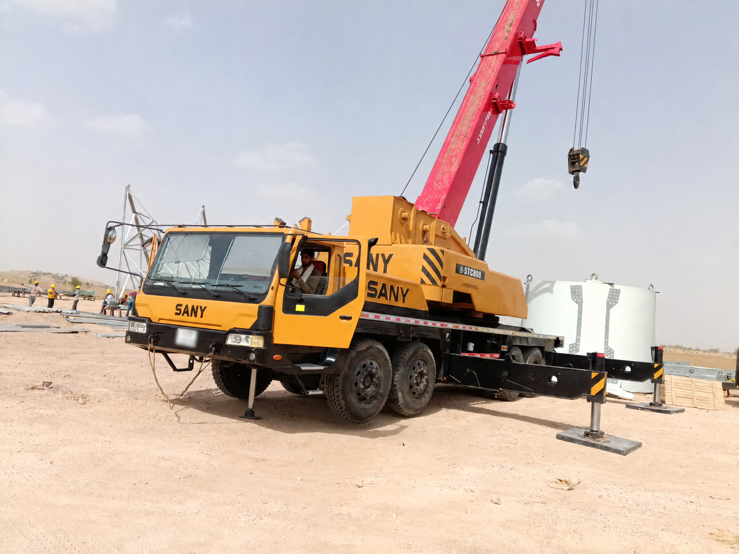
The SANY STC800 is an 80 t truck crane built for heavy lifting, long-reach boom work and highway mobility. It uses a five-section U-type 12.96-50 m boom, 10.2 m / 17.5 m jib options, 15.65 t counterweight, H-type fully hydraulic outriggers, load-sensing hydraulics and SANY safety systems.
Capacity80 t
Boom50 m
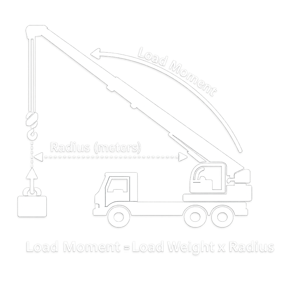
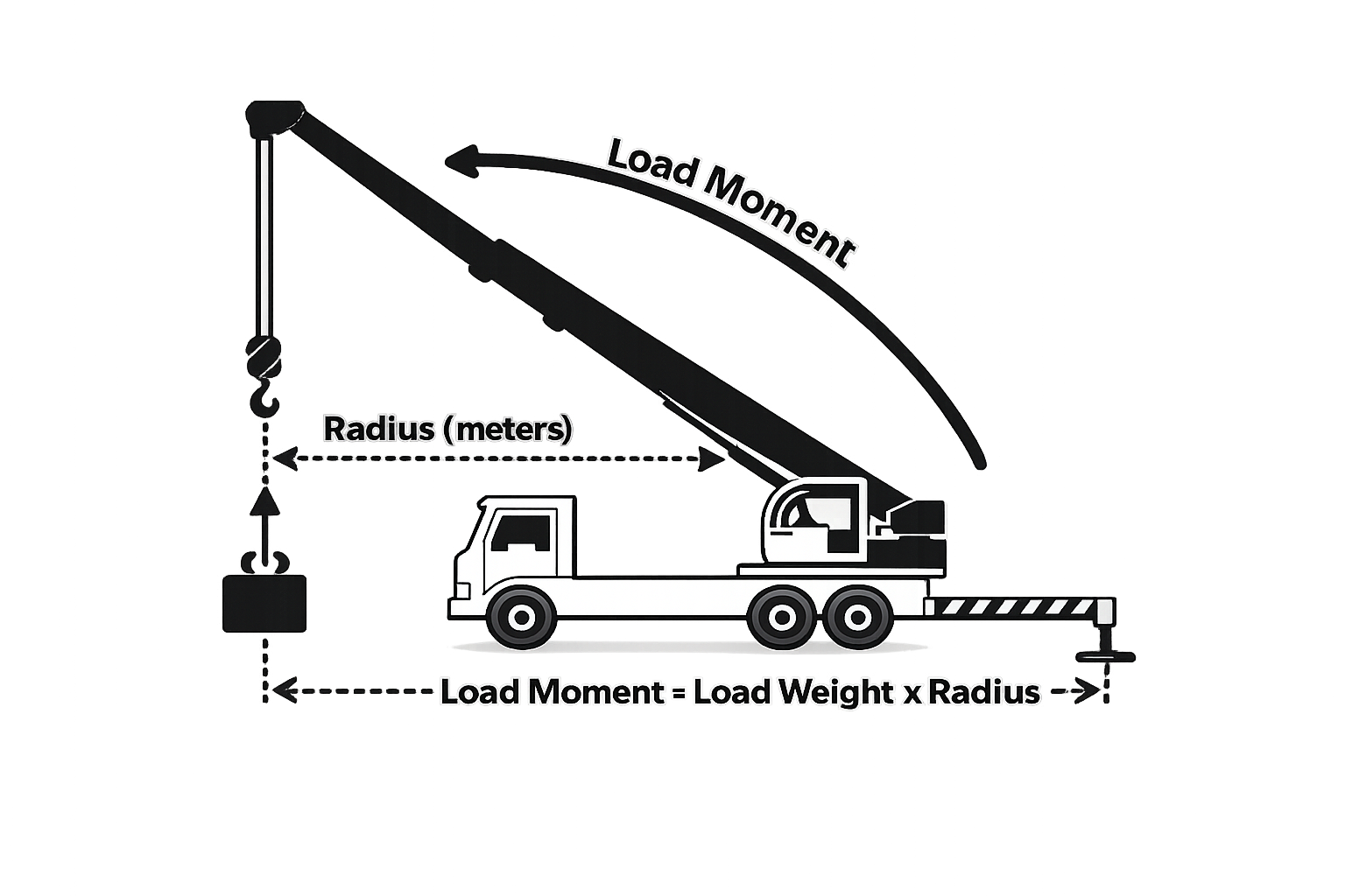
Load Moment3,293 kN.m
Engine276 kW
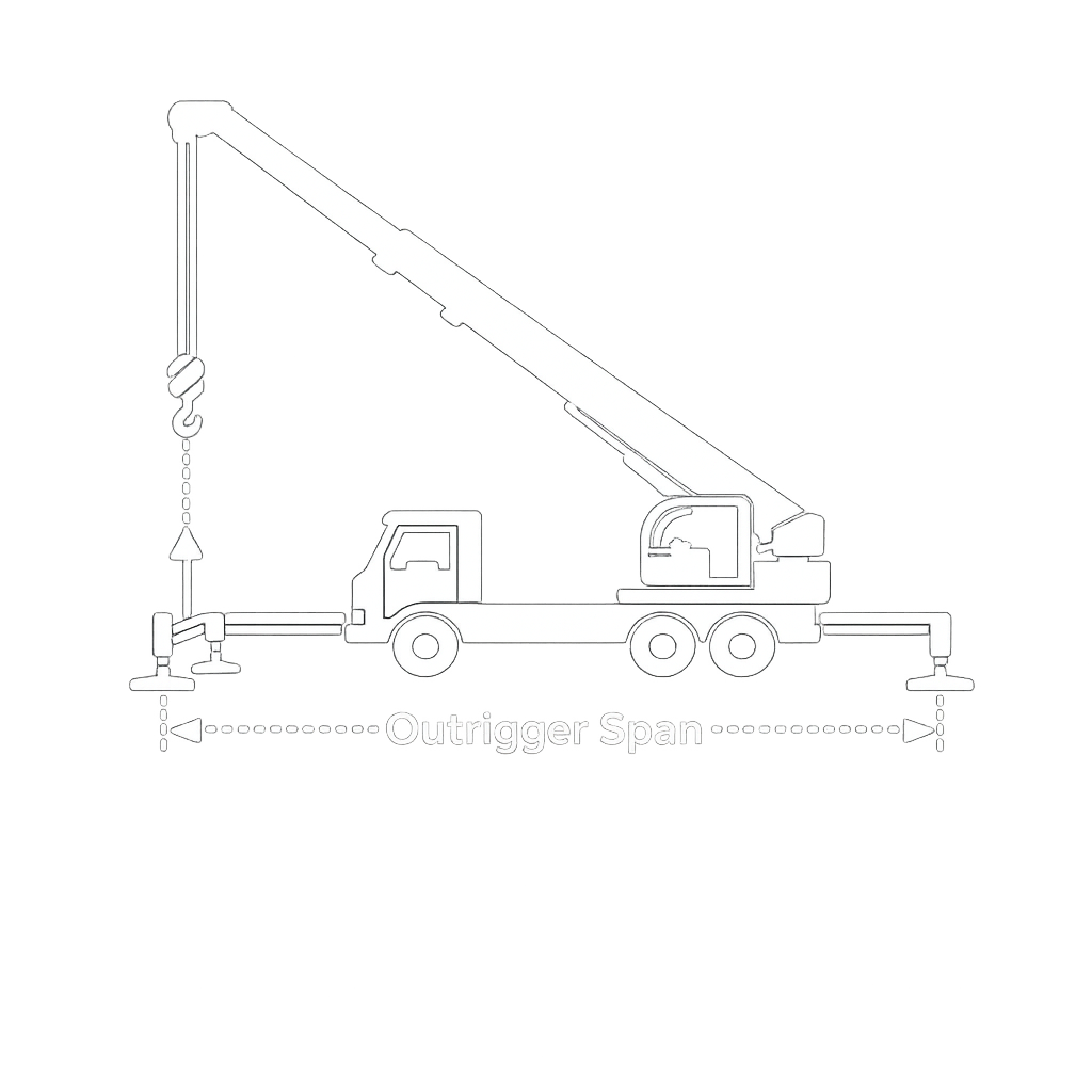
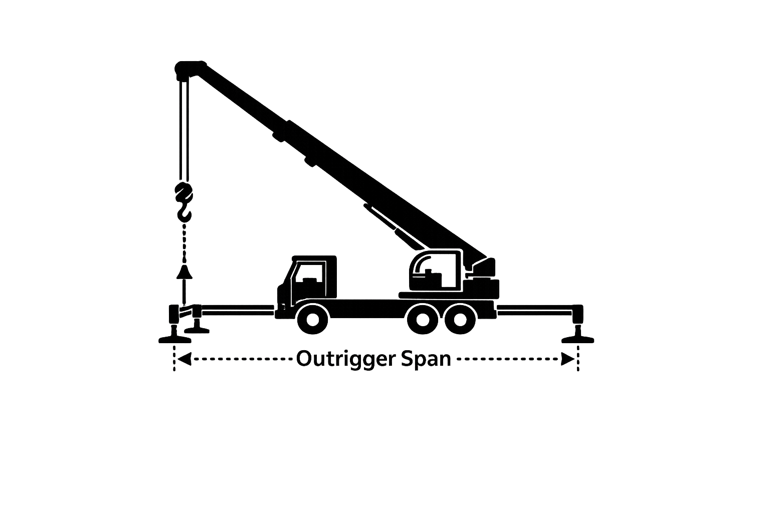
Outrigger8 x 6.43 m
Max Speed80 km/h
Key Highlights
Capacity
80 t
Load Moment
3,293 kN.m
Boom Length
12.96-50 m
Boom + Jib
67.5 m
Engine Power
276 kW @ 1900 rpm
Torque
1800 N.m @ 1000-1400 rpm
Max Speed
80 km/h
Max Gradient
44%
Outrigger Span
8 x 6.43 m
Counterweight
15.65 t
Carrier
8 x 4 x 4
Hoist Speed
130 m/min
Total Weight
50,000 kg
Dimensions
15.29 x 2.8 x 3.88 m
Hook Options
80 t / 30 t / 7.5 t
Specifications
Detailed technical specifications for SANY STC800 80T Truck Crane
Parts of Line by Boom Length12 / 11 / 8 / 7 / 6 / 5 / 4 / 3 / 3
First Cylinder Extension0% to 100% depending on boom length
Second Cylinder Extension0% to 100% depending on boom length
Jib Load Chart Setup15.65 t counterweight, fully extended main boom plus jib, fully extended outriggers, side or rear operation
Jib Lengths10.2 m and 17.5 m
Jib Offset Angles0 degree / 15 degree / 30 degree
Jib Chart Elevation Range80 degree down to 46 degree
Maximum Jib Chart Capacity6.5 t with 50 m boom + 10.2 m jib at 0 degree offset
Jib Hook7.5 t hook, 1 part of line
Working Range NoteCapacity changes with boom length, working radius, jib angle, counterweight, outrigger setup and operating zone. Verify the rated load chart before lifting.
SYSTEMS & SAFETY
Operator CabTilts up to 20 degree with safety glass, panoramic sunroof, air conditioner, adjustable seat and 10 inch touch screen
Operating ControlsTwo electronic proportional handles, pedals for engine speed and boom telescope, rocker switches for auxiliary functions
Lifting SystemDual planetary hoist drive with spring-applied brake and counterbalance valve
Luffing SystemPower-up and gravity-lower boom luffing system
Slewing SystemAxial piston fixed-displacement motor with electronic proportional speed control
Safety DevicesLoad moment indicator, anti-two block, hoist drum third-wrap protection and programmable boom height limiter
Hydraulic ProtectionCounterbalance valves on boom and hoists; lock valves on load-bearing cylinders
Electrical SystemTwo 12 V maintenance-free batteries, battery disconnect switch and CAN bus communication
SANY STC800 Maintenance Checklist
Daily pre-start checks · Service schedule by operating hours · Warning alert actions — SANY STC800 80-ton truck crane.
Daily Pre-Start Checklist
Complete all checks before every shift. Estimated time: 10–15 minutes.
Every Shift
1
Hydraulic Oil Level
With the boom fully stowed on level ground, check the hydraulic oil tank sight gauge.
Act if: below MIN or oil appears milky/foamy.
2
Engine Oil Level
Check the cold, stopped engine dipstick.
Act if: below MIN, black/gritty, or smells of fuel.
3
Gearbox Oil Level
Check the transmission level plug/dipstick; check the oil condition and level.
Act if: below minimum, discoloured, or burnt-smelling.
4
Differential Oil Level
Check front and rear axle differential level plugs; check the oil condition and level.
Act if: below minimum or an axle housing leak is visible.
5
Engine Coolant Level
Check the reservoir with the engine cold; inspect the cooling system for leakage.
Act if: below MIN, discoloured, or leaking.
6
Fuel & Water Separator
Check the fuel gauge and drain the fuel/water separator.
Act if: water/sediment is present or any fuel leak is found.
7
DEF / Urea Level
Check the Stage IV/V SCR-system tank gauge.
Act if: empty or contaminated.
8
Clutch / Brake Fluid
Check the reservoir sight glass.
Act if: below the minimum mark.
9
Air Reservoir Drain
Open each air-tank drain valve and release condensation.
Act if: excessive water/oil drains or air builds slowly.
10
Brake Air Pressure
Start the engine and confirm normal working pressure before moving.
Act if: pressure remains low or the warning stays on.
11
Lights & Signals
Test headlights, indicators, hazards and beacon; verify them during a walk-around.
Act if: any required lamp is inoperative.
12
Steering
Check steering-wheel free play and power-steering fluid level.
Act if: free play is excessive or steering feels heavy/notchy.
13
Foot & Exhaust Brakes
Test brake-pedal feel/travel and exhaust-brake operation.
Act if: pedal is soft/sinking or the vehicle pulls aside.
14
Clutch
Check pedal free play and engagement.
Act if: slipping, chattering, or noisy.
15
Batteries & Electrical
Check both 12 V maintenance-free batteries, terminals, charge indicator and disconnect switch.
Act if: corroded/loose or charge warning remains on.
16
Tyres
Inspect all tyres cold and check pressure with a gauge.
Act if: pressure is outside range, cut, cord-exposed, or unevenly worn.
17
Main & Auxiliary Wire Rope
Inspect full lengths for broken wires, kinks, corrosion and diameter loss. Main: 20 mm × 250 m; auxiliary: 20 mm × 145 m.
Act if: discard criteria are met or kinking/bird-caging appears.
18
Hook Block & Safety Latch
Inspect for cracks/deformation and verify the latch closes and locks freely.
Act if: cracked, throat opening enlarged, or latch fails.
19
Outriggers & Pads
Inspect beams, jacks, pads and locking pins. Full span: 8 m transverse × 6.43 m longitudinal.
Act if: beams are bent, jacks leak, or pins will not seat.
20
Safety Devices
Run the self-test for LMI, anti-two-block, third-wrap protection and boom-height limiter.
Act if: self-test fails, lamp/buzzer is inactive, or a fault code appears.
Safety note: do not travel or lift until defects affecting brakes, steering, tyres, wire ropes, hook, outriggers or any safety device have been corrected.
Service Schedule by Hourmeter
Use the hourmeter for scheduled service. Gearbox and axle oil changes are kilometre-based.
Complete before every shift or each 10 operating hours.
Engine & Fuel
Oil pressure and coolant
Check oil pressure; inspect coolant level and condition
CHECK
Fuel separator and DEF
Drain water separator; inspect DEF/SCR level
DRAIN
Hydraulics
Hydraulic oil, hoses and fittings
Inspect level, oil condition and the complete system for leaks
INSPECT
Crane & Safety
Wire ropes
Visual inspection of main, auxiliary and visible telescoping ropes
INSPECT
Third-wrap and anti-two-block
Function-test both protection devices and the LMI
TEST
Electrical
Batteries and terminals
Inspect both 12 V batteries and disconnect switch
INSPECT
CAN-bus instrument self-check
Confirm the cluster completes without faults
CHECK
Perform at 50 operating hours in addition to daily checks.
Engine & Air
Air-filter element
Inspect for restriction, damage and contamination
INSPECT
Chassis & Brakes
Suspension and wheel nuts
Inspect steel plate springs; check/re-torque wheel nuts to approximately 575 ± 25 N·m
CHECK
Air dryer
Inspect dryer and desiccant condition
INSPECT
Lubrication
Chassis grease points
Use No. 2 lithium-base grease; No. 3 for hot climates
GREASE
Superstructure points
Grease boom pivots, telescoping sections and sheaves
GREASE
Counterweight
Mounting and pins
Inspect the fixed/removable counterweight mountings and locking pins
INSPECT
Scheduled 500-hour service.
Engine & Fuel
Engine oil and filter
Change 23 L oil charge and filter; first fill is 25 L
CHANGE
Fuel and air filters
Replace fuel/water-separator and air-filter elements
REPLACE
Hydraulics
Hydraulic return filter
Replace the return-line element
REPLACE
Chassis & Brakes
Front-axle toe-in
Inspect and adjust if required
INSPECT
Brake linings / pads
Inspect wear and investigate increased pedal travel
INSPECT
Superstructure
Swing bearing
Grease at 500 h or every six months, whichever occurs first
GREASE
Wire ropes and telescoping ropes
Full discard-criteria inspection; adjust telescoping-rope tension
INSPECT
Winch/swing reducer and limit devices
Inspect reducer oil; adjust/calibrate third-wrap and anti-two-block protection
CHECK
Perform the scheduled 1,000-hour inspection.
Fuel Injection
Common-rail injectors
Inspect the 160 MPa common-rail system and injector operation
INSPECT
Operating Parameters
Engine oil pressure
Verify 350–550 kPa normal pressure and at least 100 kPa at idle
CHECK
Safety-device calibration
Confirm LMI, anti-two-block, third-wrap and boom-limit functions
TEST
Major hydraulic and reducer service at 2,000 hours or 12 months, whichever occurs first.
Hydraulic System
Hydraulic oil
Change the complete hydraulic oil charge
CHANGE
Hoses, fittings and filter
Detailed inspection; replace damaged hoses and service filtration
INSPECT
Winch & Swing
Reducer oil
Change winch and swing reducer oil
CHANGE
Boom, hoist and swing structure
Detailed inspection and complete lubrication
INSPECT
Long-interval items at 4,000 hours or annually where stated.
Cooling & Emissions
Coolant
Change at 4,000 h or every 12 months, whichever occurs first
CHANGE
DEF / SCR system
Complete annual system service
SERVICE
Brake Air System
Air-dryer desiccant
Replace annually
REPLACE
Kilometre-Based Driveline
Gearbox and differential oils
Change after the initial 1,000 km, then every 20,000 km; do not use the hourmeter for these items
CHANGE
Warning Alerts & Immediate Actions
RED = stop the engine or crane motion immediately. AMBER = act before continuing.
Red — Stop immediatelyAmber — Act before continuing
RED
LMI Overload Alarm
Actual load/radius exceeds rated capacity.
Immediate action: stop hoisting, luffing or telescoping; lower the load or reduce radius until the LMI confirms a safe range.
Risk if ignored: boom failure, tip-over or structural overload.
RED
Anti-Two-Block Alarm
The hook block is contacting or approaching the boom-nose sheave.
Immediate action: stop hoist/luffing motion; lower the hook or extend the boom to clear it.
Risk if ignored: snapped rope, dropped load or boom-nose damage.
RED
Hoist Third-Wrap Alarm
Too few wire-rope wraps remain on the drum.
Immediate action: stop lowering and raise the hook back onto the drum.
Risk if ignored: rope pull-out and dropped load.
RED
Engine Coolant High Temperature
Coolant temperature is above the normal range.
Immediate action: stop the engine when safe; never remove the radiator cap while hot.
Risk if ignored: overheating, warped head/block and engine failure.
RED
Engine Oil Pressure Low
Pressure has dropped below the safe minimum.
Immediate action: stop the engine immediately and check the oil level before restarting.
Risk if ignored: bearing seizure or complete engine failure.
AMBER
Hydraulic Oil Level / Temperature
Reservoir level is low or oil temperature is excessive.
Risk if ignored: pump cavitation and hydraulic damage.
AMBER
Boom Height / Angle Limiter
The boom is near its preset height or angle limit.
Immediate action: ease off the triggering function and confirm overhead clearance; do not override.
Risk if ignored: obstruction strike or over-angle damage.
AMBER
Brake Air Pressure Low
Brake-system pressure is below its normal working range.
Immediate action: stop safely and do not travel until pressure is restored.
Risk if ignored: loss of braking ability.
AMBER
DEF / Urea Low
SCR-system fluid level is low.
Immediate action: refill DEF as soon as possible.
Risk if ignored: reduced-power derate mode.
AMBER
Wire-Rope Discard Flag
Broken wires, diameter reduction, corrosion, kinking or bird-caging is present.
Immediate action: remove the rope from service and replace it before further hoisting.
Risk if ignored: sudden rope failure and dropped load.
Critical: never disable, bypass or override the LMI, anti-two-block switch, third-wrap protection or boom-height limiter. If any device malfunctions, take the crane out of service until repaired and tested.
Frequently Asked Questions
Everything you need to know about the SANY STC800 Truck Crane
The SANY STC800 has a maximum rated lifting capacity of 80 t and maximum lifting torque of 3293 kN.m at minimum boom length.
The crane uses a five-section U-type boom from 12.96 m to 50 m. With jib, the maximum boom plus jib length is 67.5 m.
The STC800 engine develops 276 kW at 1900 rpm and 1800 N.m torque at 1000-1400 rpm.
The main and auxiliary hoists both reach 0-130 m/min on single line with no load. Slewing speed is 0-1.8 r/min.
The overall dimensions are 15,290 x 2,800 x 3,880 mm. The outrigger span is 8 m x 6.43 m.
The STC800 includes load moment indicator, anti-two block system, hoist drum third-wrap protection, programmable boom height limiter, counterbalance valves and lock valves on load-bearing cylinders.