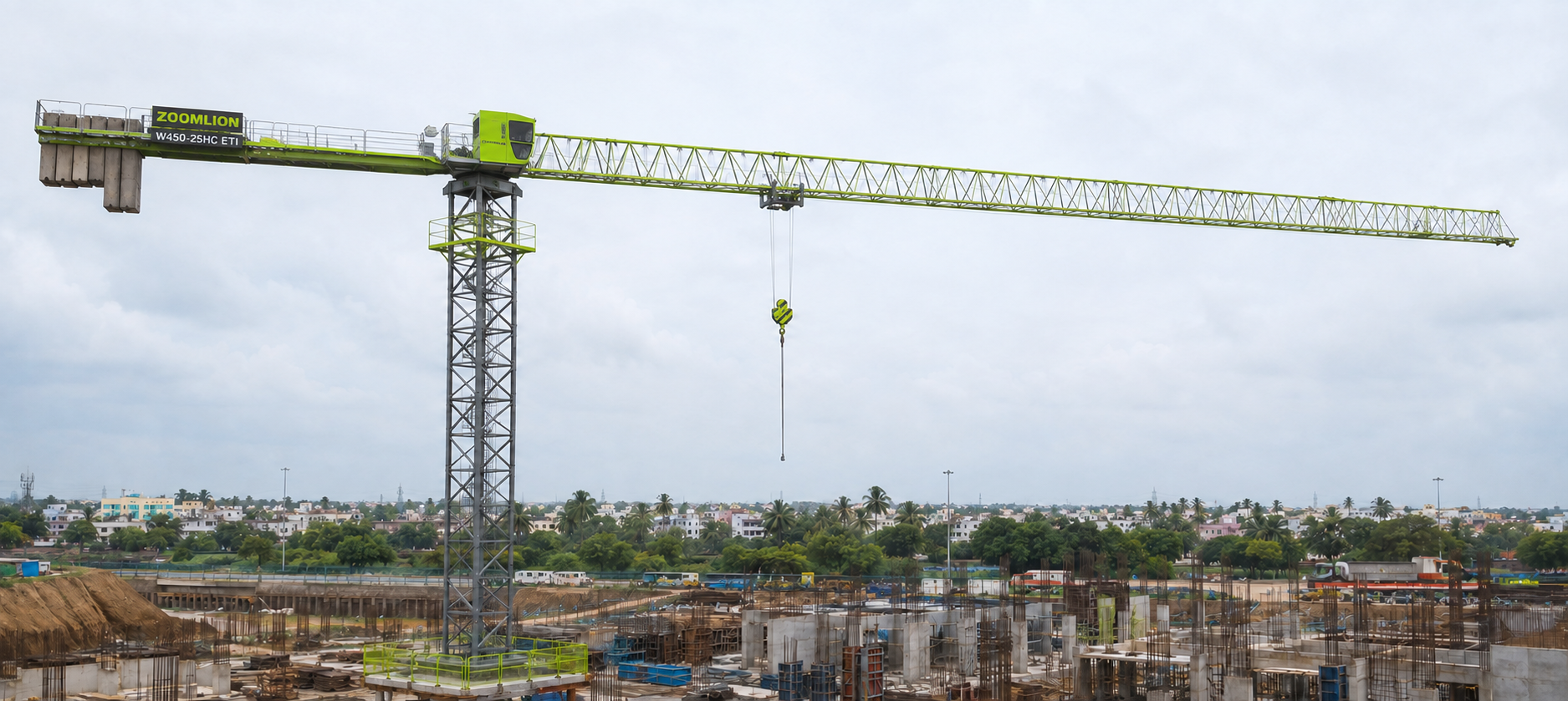
The Zoomlion W450-25HC ETI is a W450 series flat-top tower crane with 25 t maximum hoisting capacity, 80 m maximum jib, 65.7 m free-standing height and 1040 m rope capacity. The mechanism set includes H75FL63-1040 hoisting, S75CA / S75CN slewing and T110FC85-b trolleying for heavy vertical material handling on large construction sites.
Max Capacity25 t
Max Jib80 m
Free-standing65.7 m
Hoist Speed80 m/min
Tip Load2.2 t @ 80 m
Trolleying0-100 m/min
Key Highlights
Max Hoisting Capacity
25 t
Max Jib Length
80 m
Free-standing Height
65.7 m
Max Anchorage Height
396.3 m
Tip Load at 80 m
2.2 t
Hoisting Mechanism
H75FL63-1040
Rope Capacity
1040 m
Hoisting Speed
Up to 80 m/min
Slewing Speed
0-0.72 r/min
Trolleying Speed
0-100 m/min
Power Supply
380 V ±10%, 50 Hz
Installed Power
108.5 kW
Tower Section
2.5 x 2.5 x 2.85 m
Slewing Mechanism
S75CA / S75CN
Trolleying Mechanism
T110FC85-b
Specifications
Detailed technical specifications for Zoomlion W450-25HC ETI Flat-top Tower Crane
If fitted, inspect stops, track level and clearance, four-end earthing, clamps and supply cable.
Act if: a stop or earth is missing, the track is defective or obstructed, or a clamp is faulty.
5
Approved access
Inspect ladders, back loops, platforms, catwalks, rails, ropes and clear access routes.
Act if: access protection is missing, loose or damaged. Restrict access.
6
Tower connections
Check mast connections, pins, cotters, locks and indicating plates.
Act if: a lock is loose or missing, a connection is deformed or a safety plate is illegible.
7
Counter-jib ballast
Verify ballast position and fixing for the current jib configuration.
Act if: arrangement is incorrect or ballast is loose or damaged. Do not operate.
8
Hoisting and trolley ropes
Check winding, reeving, tension, rope condition and end fittings; retain at least three drum wraps at maximum payout.
Act if: a strand is broken, rope is kinked, flattened, heat-damaged, worn or an end fitting is loose.
9
Hook assembly
Inspect hook, nut or pressure plate, pulley, pins, fasteners and anti-tripping device.
Act if: cracked, twisted, abnormally open or worn, loose, or unable to close safely.
10
Hoisting brake
Function-test holding and release without load.
Act if: it fails to hold, releases late, drags or behaves irregularly.
11
Trolley brake
Test holding and release; observe drag and stopping response.
Act if: braking fails or the air gap exceeds 1.2 mm.
12
Slewing brake
Test commanded release and holding with smooth slewing response.
Act if: movement is uncommanded or there is a brake fault, impact noise or sudden power rise.
13
Rope-release device
Check correct function and unobstructed movement.
Act if: seized, damaged or ineffective. Correct before use.
14
Slewing ring and teeth
Inspect seals and exposed teeth, remove debris and confirm the tooth surface is greased.
Act if: a seal is displaced or damaged, debris enters the mesh, or noise or resistance is abnormal.
15
Fire extinguisher
Confirm the powder extinguisher is present, accessible and serviceable.
Act if: missing or unserviceable. Correct before operation.
16
ON, horn and emergency stop
Press ON, verify the horn, test emergency stop, reset and verify restart control.
Act if: motion does not stop immediately or the horn or start interlock fails.
17
No-load motion test
Test hook, trolley and slew motions; controls must move smoothly and return to zero.
Act if: motion is unexpected, a command is skipped, control does not return, or noise or vibration is abnormal.
18
Limit switches
Without load, test upper and lower hook stops and maximum and minimum trolley positions.
Act if: a stop position is incorrect or a limiter fails.
19
Load and moment safety
Check overload alarm, load and load-moment displays and percentage indication.
Act if: an alarm or display is absent, inaccurate or bypassed. Stop and recalibrate.
20
Displays and warning devices
Check trolley position, hook height, wind speed, voltage, beacon, sound signal and lamps.
Act if: a safety-related indication or signal is unavailable.
21
Cabinet and electrical condition
Inspect doors, breakers, display, indicators, cooling openings, moisture and contamination.
Act if: a component is burnt, water has entered, protection has tripped or live equipment is exposed.
22
Lighting and wipers
Check cab lighting, external warning lights and windscreen wipers required for visibility.
Act if: required visibility or warning lighting is unavailable.
Wind rules: assembly, dismantling or configuration change requires gusts below 50 km/h. In-service operation requires gusts below 72 km/h. Do not operate the climbing pump above Beaufort force 4.
Maintenance Schedule
Use operating hours for the relevant mechanism and the earlier limit where hours and calendar time are both stated.
Recalibration: recalibrate safety devices after climbing, jib-length changes, or replacement of the hoisting rope, trolley, hoisting or trolley mechanism, load sensor or another related safety component.
Complete the installed-configuration checks before service and lifting.
Start-up and erection
Slewing ring and teeth
Lubricate the raceway and exposed gear teeth.
GREASE
Ropes, hook and structure
Inspect ropes, end fittings, hook, framework, welds, connections, twist compensator and reducer oil.
INSPECT
Pins, rollers and climbing oil
Lubricate climbing pins, guide rollers and all erection pins; check climbing oil level and quality.
SERVICE
Daily mechanism checks
Brakes and rope-release device
Function-test hoisting, trolley, slewing and any travelling brake plus the rope-release device.
CHECK
Reducer and slewing teeth
Check reducer temperature and noise; inspect and grease exposed teeth and inspect sealed pulley bearings.
INSPECT
Controls and safety devices
Function-check limiters, displays, warnings, brakes, sensors and cabinet condition before operation.
TEST
Shorten slewing-ring lubrication intervals in rain, humidity, dust, temperature variation or continuous operation.
Weekly
Ropes, drum and pulley points
Lubricate hoisting and trolley ropes, winch drum bearing and only pulley locations fitted with grease points.
GREASE
Electrical and safety
Inspect electrical controls, cable, wiring, limiters and safety devices.
INSPECT
Monthly / every 2–3 weeks
Hook and structure
Measure hook opening, twist and wear; inspect vital framework, welds, bolts and pins.
MEASURE
Reducer and slewing teeth
Check reducer level and leakage when cool; clean exposed teeth and renew their grease coating.
CHECK
Electrical detail inspection
Inspect supply, phase sequence, voltage, cables, earthing, insulation, connectors, contactors, relays, brakes and sensors every 2–3 weeks.
INSPECT
First month
Inspect high-tensile bolt connections and top up filtered climbing-system oil to the upper mark.
CHECK
Every 3 months
Hoisting reducer vent
Clean the vent cover and filter.
CLEAN
Trolley brake
At 450 h or 3 months, remove contamination and set a uniform 0.6 mm air gap.
ADJUST
Initial-hour services establish the long-term lubrication and bolt-preload baseline.
100 and 500 hours
Slewing raceway
Lubricate every 100 h while slewing slowly until old grease is displaced at the seal.
100 H
Slewing-ring bolts
Check and restore preload after the first 100 h and every 500 h thereafter.
TORQUE
400-hour reducer service
Oil condition
Check water content after the first 400 h and at least annually.
CHECK
Initial oil change
Change the hoisting reducer oil with L-CKD 150; fill cooled oil halfway on the dipstick.
CHANGE
Brake and coupling settings
Hoisting brake
Braking moment 1250–1300 N·m; pusher stroke 20 ±2 mm rated and 5 mm minimum.
SET
Clearances
Balance lever: at least 8 mm to bottom plate and 5 mm to brake wheel; brake-wheel run-out no more than 0.7 mm.
MEASURE
Trolley brake and coupling
Air gap 0.6 mm standard, 1.2 mm maximum. Coupling alignment: axial ≤4 mm, radial ≤1.5 mm, angle ≤1°.
ADJUST
Complete earlier recurring inspections and lubrication whenever a long interval becomes due.
Six-month and annual
Six months
Lubricate all nipples; inspect the twist compensator and high-tensile bolts, and grease the bolt connections.
SERVICE
1500 h / annual
Change motor-bearing lubricant after 1500 h and at least annually; inspect hook assembly and lubricate the cab front-window hinge.
ANNUAL
2000 hours
Gearboxes
Renew slewing and trolley reducer lubricants and travelling gearbox lubricant if fitted.
RENEW
Hoisting brake thrust fluid
Change with DB-25 only.
CHANGE
2400 and 5000 hours
Climbing hydraulic oil
Change filtered L-HM 46 completely at 2400 h.
2400 H
Hoisting reducer oil
After the initial 400 h change, renew L-CKD 150 every 5000 h or 18 months.
5000 H
Climbing balance-valve O-ring
Replace the O-ring between the balance valve and cylinder every two years.
2 YEARS
Climbing and electrical work must be performed by trained personnel with the crane secured.
Climbing hydraulic system
Before climbing
Check cylinder connection, hoses, joints, oil, motor direction and smooth manual-valve operation.
CHECK
Fill and cleanliness
Use only L-HM 46 through 10 μm filtration; reach NAS 1638 class 7–8 cleanliness and fill to the upper mark.
FILTER
Pressure and idle return
Maximum setting 31.5 MPa. After long idle, run the pump station for more than 30 minutes before use.
31.5 MPA
Weather
Fit a rainproof shield and do not operate above Beaufort force 4.
PROTECT
Electrical and safety cycles
Daily
Check cabinet closure, breakers, display, horn, sensors, limits, brake indication, voltage and warnings.
TEST
Erection / every 2–3 weeks
Inspect supply, phase sequence, service voltage, cable condition, earthing, insulation, connectors, contactors, relays, brakes and sensors.
INSPECT
Known-load verification
Verify load-display accuracy and load and moment limiter actuation with a controlled test.
VERIFY
Control-cabinet settings
Thermal and humidity
Cooling fan +40°C; heater 0°C; heating humidity RH 80%.
SETTINGS
Voltage protection
Overvoltage 420 V; undervoltage 340 V; monitoring delay 2 s.
PROTECT
Inspection & Removal Limits
Remove any component that reaches a rejection limit before lifting resumes. Welding repair of the hook is prohibited.
Hook
Opening
Measure monthly; replace above 110% of the initial opening.
110%
Twist
Replace when torsion exceeds 10°.
10°
Section wear
Replace when wear exceeds 5% of original section height H.
5%
Shank and latch
Replace below 95% original shank diameter; correct a latch that does not form a closed cavity.
95%
Wire rope
Strand and diameter
Discard for a complete strand fracture or diameter reduction of 7% or more.
DISCARD
Localized breaks and terminations
Discard close groups of broken wires; investigate termination breaks and remake only when permitted.
INSPECT
Deformation, heat and corrosion
Discard for severe kink, flattening, bend, harmful waviness, heat or arc damage, serious corrosion or lost elasticity.
DISCARD
Drum reserve
Maintain at least three full wraps at maximum payout.
3 WRAPS
Pulleys and trolley
Pulley groove
Replace for indentation, groove-depth increase of 30%d, groove radius outside 0.525d–0.6d, cracks or flange damage.
REPLACE
Sealed pulley bearings
Inspect daily for leakage, seal damage, noise, resistance and clearance; do not lubricate.
DAILY
Trolley side roller
Replace when diameter wear reaches 5%.
5%
Tower pins
Main-chord rabbet movement
Maximum permitted shake after pin installation is 0.7 mm; stop and arrange specialist inspection above this limit.
0.7 MM
Warning Alerts & Immediate Actions
Red means stop and isolate; amber means correct before continuing; green marks planned service due.
Red — StopAmber — ActGreen — Service
RED
Wind limit reached
Action: land the load safely and stop lifting when gust reaches 72 km/h or the applicable load-area limit.
RED
Temperature outside range
Action: cease operation below −20°C or above +40°C until conditions return to range.
RED
Brake fault
Action: stop and isolate the affected mechanism; service and function-test before return.
RED
Limiter or sensor fault
Action: stop lifting, recalibrate and complete a controlled verification test.
RED
Wire-rope discard condition
Action: tag out the crane, replace the rope and verify reeving and end fittings before testing.
RED
Hook rejection condition
Action: remove and replace the hook. Do not weld-repair it.
RED
Structural anomaly
Action: stop and secure the crane for specialist inspection if cracking, deformation, looseness or abnormal noise is found.
RED
Slewing noise or power rise
Action: stop immediately and inspect the slewing bearing, gears and drive.
RED
Climbing wind above limit
Action: do not use the pump station above Beaufort force 4; secure the crane.
AMBER
Hydraulic oil foaming
Action: clean the tank and system and refill with filtered L-HM 46 before climbing.
AMBER
Reducer abnormal condition
Action: stop the mechanism and check oil, vent, seals and reducer condition.
AMBER
Slewing seal damaged
Action: reset or replace the seal promptly and renew contaminated grease.
GREEN
100-hour service due
Action: lubricate the slewing raceway and check bolt preload at the first 100 h.
GREEN
400-hour reducer service due
Action: check water content and change L-CKD 150, filling halfway on the dipstick when cool.
GREEN
450-hour trolley brake due
Action: clean and inspect the brake and set a uniform 0.6 mm air gap.
Lubricants & Service Fill Rules
Fill by dipstick, level mark or installed gearbox label; do not estimate service quantities.
Gearboxes
Hoisting gearbox
L-CKD 150 closed-gear oil; fill cooled oil halfway on dipstick. Change at 400 h, then 5000 h / 18 months.
L-CKD 150
Trolley gearbox
000# lithium grease from −20°C to +40°C; use label quantity and renew at 2000 h.
000#
Trolley low-temperature
7412# semi-fluid gear grease from −40°C to −20°C. Do not mix products.
7412#
Slewing gearbox
000# lithium grease from −20°C to +40°C; use label quantity and renew at 2000 h.
000#
Slewing low-temperature
7023B# grease from −50°C to −20°C. Do not mix products.
7023B#
Slewing ring & ropes
Slewing raceway
2# EP lithium-base grease; fill while slewing until old grease is displaced. Every 100 h.
2# EP
Exposed gear teeth
ZG-S graphite calcium grease; clean debris and coat daily or as required.
ZG-S
Hoisting and trolley ropes
ZG-SSY1405-65 graphite calcium spray grease; apply weekly or by condition without excess.
SPRAY
Bearings & grease points
Drum and rolling bearings
Calcium-based grease; weekly for drum and six-monthly for fitted nipples.
GREASE
Pulley grease points
ZG-2 winter or ZG-5 summer calcium grease, only where a fitting exists.
ZG-2 / ZG-5
Sealed pulley bearings
Non-lubricating type; inspect daily and do not add grease.
NO GREASE
Anti-twist bearing
ZG-1 molybdenum-disulfide calcium grease at erection and six-month checks.
ZG-1
Hook bearing
Lubricate at hook service without contaminating rope or brake surfaces.
SERVICE
Hydraulic & brake systems
Climbing pump station
L-HM 46 anti-wear hydraulic oil through 10 μm filtration; fill to upper mark, top up after first month and change at 2400 h.
L-HM 46
Hydraulic cleanliness
Reach NAS 1638 class 7–8 before starting. Never mix oil types or add unfiltered oil.
FILTER
Brake thrust unit
Use DB-25 brake oil only and change at 2000 h.
DB-25
Capacity rule: numeric service capacities are not specified for these points. Use only the installed dipstick, level mark or gearbox label.
Frequently Asked Questions
Everything you need to know about the Zoomlion W450-25HC ETI Flat-top Tower Crane
The Zoomlion W450-25HC ETI has a maximum hoisting capacity of 25 t.
The maximum jib length listed for the W450-25HC ETI is 80 m.
The W450-25HC ETI has a maximum free-standing height of 65.7 m in the outrigger fixed configuration.
The mechanism table lists hoisting speeds up to 80 m/min, slewing speed of 0-0.72 r/min and trolleying speed of 0-100 m/min.
The hoisting mechanism has 1040 m rope capacity. The electrical supply is listed as 380 V (±10%), 50 Hz.