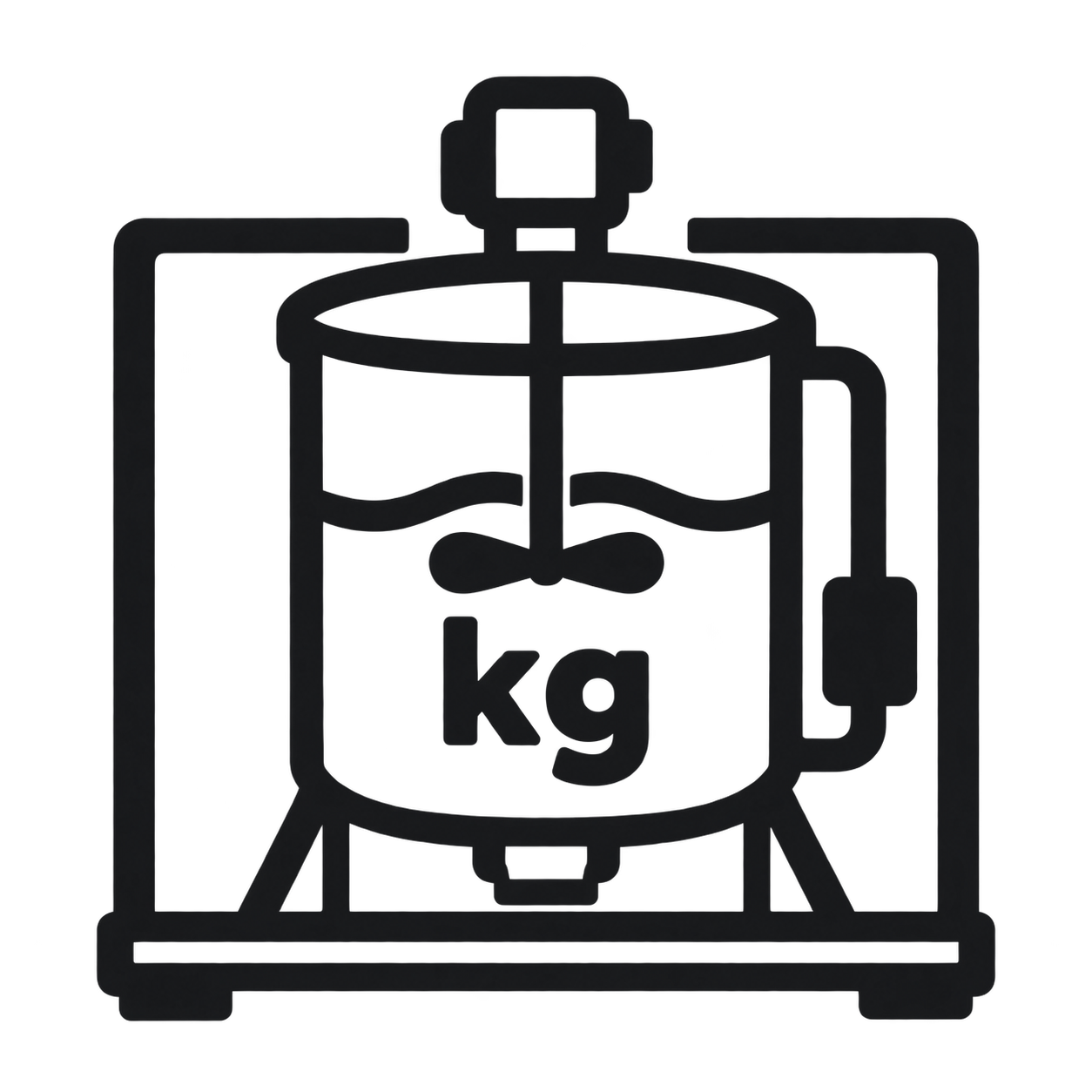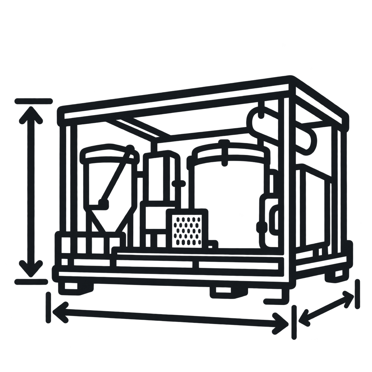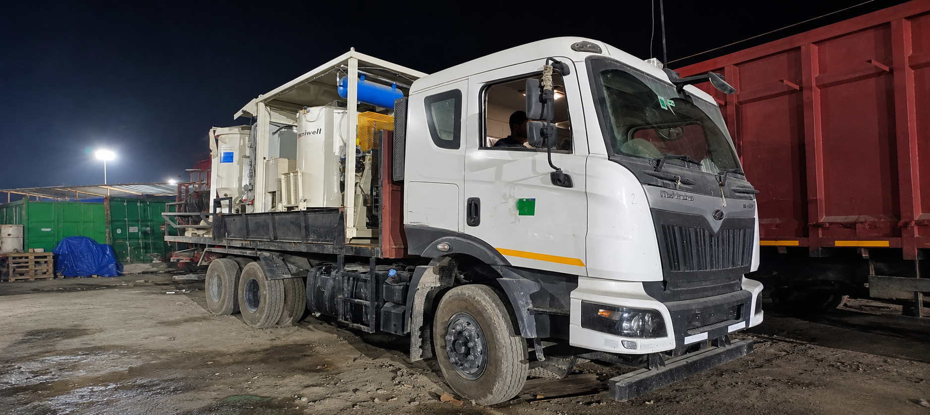
The Tecniwell TWM 30 is an integrated grout mixing plant that can be configured on a suitable carrier chassis for mobile site deployment. It combines a 2,000 L mixer, 4,000 L agitator, 1,600 L water tank, booster pump, air system, electronic load-cell weighing, PLC control with a 7-inch touch-screen and USB production recording. Maximum hourly mixing capacity is 30 m³/h.
Technical data for the Tecniwell TWM 30 grout mixing plant. Carrier-truck specifications depend on the chassis and mounting arrangement.
Daily inspection and cleaning, weekly preventive maintenance, shutdown storage and diagnostic actions for the TWM 30.
Complete once per operating day and follow the stated machine-state requirement for each task.
Plant ON: read the valve-circuit gauge. Correct range: 5–6 bar.
Act if: pressure is outside range, unstable or falls abnormally.
Plant ON: read the silo-blower air gauge. Correct range: 7–8 bar.
Act if: pressure is outside range or the blower circuit leaks.
Plant OFF: confirm the reservoir level is between MIN and MAX.
Act if: level is low/high, oil is contaminated or the reservoir leaks.
Plant ON, manual mode: admit water and run one complete mixing cycle through the agitator piping, booster pump and discharge.
Act if: flow is obstructed, leakage occurs or clear discharge cannot be established.
Plant OFF and isolated: remove residual grout from both tanks and clean the screening basket.
Act if: hardened deposits remain or safe isolation cannot be confirmed.
Flush for at least 10 minutes, or until clear water exits the grout delivery pipe to the downstream pumping unit.
Act if: clear discharge is not achieved or a line remains obstructed.
Plant OFF: clean the water filter as part of the daily cleaning intervention.
Act if: the filter is damaged, blocked or cannot be restored cleanly.
Remove the basket from its seat and clean it thoroughly.
Act if: it is damaged, distorted, blocked or cannot be correctly reseated.
Wash with service water. Do not use solvents or aggressive products.
Act if: water could contact unsafe live equipment or cement contamination remains.
Restore all guards, tank-cover locks and safety devices before returning the plant to service.
Act if: any guard, cover lock, interlock or emergency stop is missing, damaged or bypassed.
Record gauge readings, cleaning completion, defects, actions taken and the current hour-counter reading.
Act if: a safety-critical defect remains open or the plant configuration is uncertain.
The plant schedule uses weekly, condition-based and component-supplier frequencies rather than fixed plant operating-hour intervals.
Belt-drive bearings
OFF: Lubricate the bearings. Confirm the correct bearing-grease grade from machine-specific documentation before filling.
Mixer drive belt
OFF: Remove the protective housing, inspect tension and wear, adjust if necessary and replace the belt if worn.
Booster-pump seal
ON visual check: Inspect the seal for leakage. Use the fitted pump documentation for further service.
Recirculation & transfer valve sleeves
ON inspection / OFF replacement: Clean valve bodies and check for leakage. Empty and isolate the mixer, piping and pneumatic supply before sleeve replacement.
Lower-paddle scraper
OFF: Inspect the rubber scraper blade for wear. Tank intervention requires one technician working and a second technician as safety watch.
Controls & compartment
Safe state: Clean the control board, electrical cabinet exterior, data printer, viewing glass and ceiling lamp.
Noise & vibration observation
ON observation: Monitor the mixer for abnormal vibration or noise during operation.
Impeller inspection
OFF inspection: If abnormal, isolate and empty the mixer, remove the lower access screw/plug, inspect the impeller and replace it if worn.
Identify fitted compressor
Record compressor make, model and serial number before applying any operating-hour service interval or consumable specification.
Component service
Apply oil, filter, belt/coupling, condensate and other service tasks only from the confirmed compressor documentation.
Storage actions differ for inactivity of one week or less and for periods longer than one week.
Storage location
Store the plant in a sheltered, dry location.
Water & grout system
Leave the water tank completely empty. Drain and clean the mixer, agitator tanks and piping.
Compressor
Drain compressor condensate according to the fitted compressor documentation.
Additional preservation
No additional maintenance intervention is specified for short-term inactivity.
Storage & corrosion control
Store sheltered and dry. In high humidity, apply a thin film of lubricating oil to exposed mechanical parts and protect vulnerable unpainted parts.
Water & grout system
Empty the water tank and drain and clean the mixer, agitator tanks and all associated piping.
Load cells
Grease using the serial-specific approved product; do not select a grease grade by assumption.
Mixer belt drive
Grease the mixer belt-drive mechanism with the confirmed approved bearing grease.
Compressor
Drain condensate and complete the storage actions specified for the fitted compressor.
Electrical supply
Disconnect power cables and protect terminations from contamination and moisture.
Release inspection before restart
Remove preservation materials, inspect for corrosion or moisture, reconnect through authorised personnel, restore guards, confirm free drainage, verify safety devices and complete the daily checklist before production.
Use the indicated action as the first response. Stop and isolate the plant before any intrusive inspection.
A power interruption has compromised operating conditions.
Action: Identify and remove the cause, then resume the mixing cycle only through the normal restart procedure.
If ignored: unexpected or incomplete cycle state.
Electrical phases are reversed and motors rotate in the wrong direction.
Action: Qualified electrical personnel must correct the phase sequence at the external connector or main electrical panel.
If ignored: reverse rotation and equipment damage.
Pneumatic-valve circuit pressure is at or below 4 bar.
Action: Confirm compressor operation and inspect the pneumatic circuit piping for leakage.
If ignored: valves may not operate reliably.
A motor fault has tripped a protective breaker.
Action: Identify the affected motor, check electrical input and mechanical load, remove the fault or replace the motor, then reset the breaker.
If ignored: motor, cable or driven-equipment damage.
Foreign material may be in the mixer, or the impeller may be worn or damaged.
Action: Stop and isolate. Check for foreign bodies and inspect the impeller; replace if necessary.
If ignored: progressive impeller or mixer damage.
Foreign material, insufficient grout level or a worn lower-paddle rubber scraper may be present.
Action: Stop and isolate. Remove foreign bodies, confirm product level and inspect the scraper blade; replace if worn.
If ignored: paddle, scraper or tank damage.
Detailed diagnosis depends on the compressor fitted to the plant.
Action: Stop the compressor if unsafe and follow the confirmed compressor documentation.
If ignored: compressor or receiver-system failure.
Before maintenance, place the main I/O switch in O, lock it, post a maintenance-in-progress notice and control pneumatic and stored energy. Restore guards and safety devices before restart.
Indicator-level actions do not replace machine-specific electrical settings, breaker values, wiring diagrams or compressor service data. Use the installed electrical drawings and confirmed component manuals for those tasks.
Key specifications and maintenance information for the Tecniwell TWM 30 grout mixer plant and truck-mounted deployment configuration