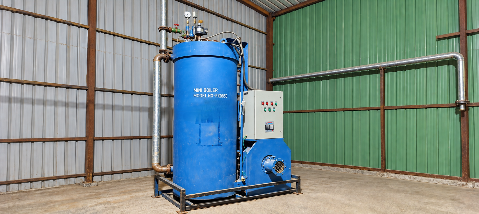
A compact three-pass, once-through, forced-circulation steam generator designed for consistent process steam. The RXD 850 combines reverse-flame combustion, a membrane coil, economiser-optimiser heat recovery and cyclonic steam separation.
Steam Capacity850 kg/hr
Design Pressure10.54 / 17.5 kg/cm²g
Oil / Gas Efficiency88% / 87.5%
Fuel OptionsHSD / LDO / FO / NG / LPG
Dry Weight1,100 kg
Steam DrynessUp to 92%
Key Highlights
Steam Capacity
850 kg/hr at F&A 100°C
Design Pressure
10.54 / 17.5 kg/cm²g
Oil / Gas Efficiency
88% / 87.5%
Multi-fuel Firing
HSD, LDO, FO, NG and LPG
Generator Design
Three-pass, once-through, forced circulation
Reverse Flame Technology
Consistent combustion and thermal efficiency
Membrane Coil
Uniform heat transfer and enhanced coil life
Economiser-Optimiser
Heat-loss and pitting-corrosion reduction
Cyclonic Steam Separator
Steam dryness up to 92%
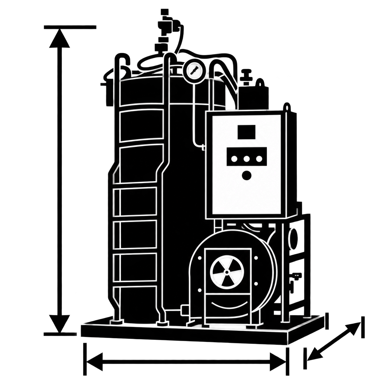
Overall Dimensions
1,770 × 1,420 × 2,890 mm
Dry Weight
1,100 kg without separator
Connected Load
3.50-6.87 kW by firing configuration
HSD Consumption
49.68 kg/hr
Natural Gas Consumption
61.71 Nm³/hr
Plug & Play Unit
Compact N-IBR design
Specifications
Technical specifications for the Thermax Revomax RXD 850
Stop and report if: fuel vapour, pooled oil, blocked exit, poor ventilation or emergency control is inaccessible.
14
Operating log
Review the previous shift record, alarms, abnormal trends and unresolved defects. Record the pre-start result.
Stop and report if: a safety defect is unresolved or the cause of an alarm or abnormal trend is unknown.
Maintenance Schedule & Service Triggers
Select a system group. Items are triggered by operating condition, not a fixed hour interval.
Applies continuously while the unit is in service.
Operation
Pre-start inspection
Complete the daily checklist and review unresolved defects. Trigger: before each start.
RECORD
Operating monitoring
Monitor water supply, pressure, flame alarms, leakage, noise and vibration. Trigger: continuously while operating.
MONITOR
Operating hour record
Record the hour meter with alarms, defects and maintenance events. Trigger: at shift or operating-record close.
RECORD
Water treatment and feed system.
Water treatment & feed
Water treatment
Review the approved site water test result and verify the treatment plant is in service. Trigger: before continued operation and whenever water quality is doubtful.
INSPECT
Filters & strainers
Inspect for restriction, sediment, damage and leakage. Trigger: when flow is abnormal or restriction is indicated. Clean or replace only after isolation and depressurisation.
INSPECT
Feed pump & motor
Inspect delivery, leakage, noise, vibration, temperature, coupling and guards. Trigger: when performance changes or a defect is observed.
INSPECT
Burner and fuel system.
Burner & fuel
Fuel train
Inspect for leakage, unstable pressure or flow, and damage to valves, hoses, regulators or fitted oil-heating equipment. Trigger: before start and whenever combustion becomes unstable.
ISOLATE IF LEAK
Burner air path
Inspect accessible intake and burner areas for dirt, soot, obstruction and loose parts. Trigger: when flame, smoke or airflow condition changes.
INSPECT
Ignition & flame safeguard
Check start sequence and flame proving without bypassing any interlock. Trigger: after a lockout, ignition fault, or at authorised service.
TEST
Combustion air fan
Trend abnormal noise, vibration, overheating and motor load where available. Trigger: when the healthy baseline changes.
INSPECT
Coil, steam and heat recovery.
Coil & heat recovery
Coil external condition
Inspect accessible areas for leakage, corrosion evidence, scale tracks and abnormal temperature or pressure behaviour. Trigger: defect or trend change, during an approved shutdown. Pressure-part work requires a Thermax-approved procedure and competent personnel.
INSPECT
Coil internal condition & descaling
Evaluate only from approved water analysis trends and the current Thermax inspection method. Trigger: only when applicable OEM criteria require it. Do not select chemicals, quantity, concentration, temperature or duration from this guide.
DESCALE PER OEM
Economiser & optimiser
Check for leakage, restriction and abnormal heat recovery performance. Inspect internally only when isolated. Trigger: when performance changes, during an approved planned shutdown.
INSPECT
Steam separator & outlet
Check for leakage, unstable steam delivery, carryover symptoms and damaged supports or insulation. Trigger: when symptoms occur, during an approved shutdown.
INSPECT
Blowdown & drains
Check valve condition, leakage and safe discharge routing. Operate only under the approved procedure. Trigger: as directed by the applicable water quality and operating procedure — no universal daily frequency is stated in this guide.
CHECK
Controls, safety and instrumentation.
Controls & safety
Safety valve & pressure protection
Check for leakage, obstruction, damaged seals or signs of tampering. Do not adjust in service. Trigger: test and certification only at the required OEM or statutory interval, using the certified installed set pressure — not the brochure design pressure.
TEST PER OEM
Pressure & temperature instruments
Check condition, plausibility and agreement with process behaviour. Trigger: after abnormal indication or repair, or at the approved calibration interval, using a traceable calibration.
CALIBRATE
Interlocks & shutdowns
Verify function only under an authorised test plan. Never defeat a trip or permissive. Trigger: after relevant repair, a nuisance trip, or at the approved proof-test interval, using the serial-specific cause-and-effect chart.
PROOF TEST
Casing and structure.
Casing & structure
Refractory, insulation & casing
Inspect visible condition, access covers, fasteners, insulation and hot-spot evidence. Trigger: when damage or hot spots are observed, during a planned shutdown. Repair before operation if personnel or equipment can be exposed to heat or gas.
INSPECT
Piping supports & valves
Inspect for leakage, corrosion, loose support, damaged insulation and difficult operation. Trigger: when a defect is observed and during planned inspection. Depressurise, cool and isolate before intrusive work.
INSPECT
Warning Alerts & Immediate Actions
STOP means shut down and isolate immediately using the approved procedure. ACTION means correct the condition before normal operation continues.
STOP — Shut downACTION — Correct
STOP
Low or lost feedwater
Action: stop firing. Verify water source, pump, valves and level controls. Do not restart until the cause is corrected. Risk if ignored: coil overheating and pressure-part failure.
STOP
Uncontrolled or unreliable pressure
Action: stop firing and isolate. Keep clear of discharge. Have pressure controls, gauge, outlet and safety devices checked. Risk if ignored: overpressure, hot release and major equipment damage.
STOP
Fuel or gas leak
Action: do not operate electrical switches in a gas cloud. Isolate fuel from a safe location, stop ignition sources, ventilate and follow the emergency plan. Risk if ignored: fire, explosion and personnel injury.
STOP
Flame failure, delayed ignition or repeated lockout
Action: stop and allow the approved purge sequence. Do not repeatedly reset. Inspect fuel, ignition, air and flame-safeguard systems. Risk if ignored: fuel accumulation, furnace explosion or burner damage.
STOP
Suspected coil steam or hot water leak
Action: stop firing, isolate, keep personnel clear and allow safe depressurisation and cooling. Do not approach a jetting leak. Risk if ignored: severe burns, pressure-part damage and loss of containment.
STOP
Backfire, blocked flue or combustion gas leakage
Action: stop firing and isolate. Inspect the air path, burner, furnace, flue and chimney only after safe cooling. Risk if ignored: fire, explosion, carbon monoxide exposure and heat damage.
STOP
Severe fan vibration, rubbing or overheating
Action: stop and isolate. Inspect with competent personnel before restart. Risk if ignored: mechanical failure, fire and loss of combustion air.
STOP
Electrical burning, water ingress or exposed conductor
Action: isolate electrical supply and use qualified electrical personnel. Do not restart after a simple alarm reset. Risk if ignored: electric shock, fire and control failure.
ACTION
Water treatment unavailable or result outside approved limit
Action: stop or hold operation as required by the approved water-quality plan. Restore treatment and obtain an acceptable test result. Risk if ignored: scaling, overheating, efficiency loss and coil damage.
ACTION
Wet steam carryover or water hammer symptoms
Action: reduce risk to the process, stop if severe, and investigate water quality, operating control, separator and coil condition. Risk if ignored: process contamination, piping damage and poor heat transfer.
ACTION
Repeated alarm or interlock trip
Action: record the alarm, diagnose the cause and complete an authorised functional check. Never bypass the protection. Risk if ignored: unsafe restart and hidden equipment failure.
Fluids & Water Treatment
No complete serial-specific capacities and consumables chart was available. Use the identification controls below instead of generic values.
Feedwater & fuel
Feedwater
Treated water meeting the requirement issued for the installed RXD 850 and site treatment system. Confirm approved limits, sampling point, test method and corrective action from the serial-specific Thermax document.
CONFIRM
Oil fuel
Fuel grade and burner condition specified for the installed oil burner and purchase specification. Confirm burner, nozzle, pump, heater and viscosity requirement from installed component records.
CONFIRM
Gas fuel
Gas type, pressure, flow and train arrangement approved for the installed burner. Confirm regulator, valve train, leak test and commissioning data — do not use a generic pressure value.
CONFIRM
Lubrication & treatment chemicals
Pump, motor & fan lubrication
Lubricant specified by each fitted component manufacturer. Read the component nameplate and manual before adding or changing lubricant.
CONFIRM
Water treatment chemical & resin
Product approved for the installed treatment plant and water analysis. Use the supplier procedure and current safety data sheet; regenerate or replace by measured condition and approved plan.
CONFIRM
Coil cleaning / descaling material
Only the product and method approved in the current Thermax work instruction. Chemical type, concentration, quantity, temperature, duration, neutralisation and rinse acceptance are outside this guide.
OEM APPROVED ONLY
Parts Identification & Ordering Control
Pressure parts & drives
Pressure parts & coil
Confirm unit model, serial number, pressure rating and current Thermax bill of material. Do not substitute a coil, valve or gasket from a tender list or another RXD installation.
VERIFY
Feedwater pump
Confirm pump make, model, serial number, duty and motor nameplate. RXD 850 installations may use different pump configurations — order seals, valves and internals for the fitted pump.
VERIFY
Fan & motor
Confirm fan impeller, motor and bearing nameplates — speed, rotation, balance and bearing details — before service or replacement.
VERIFY
Burner, safety & controls
Burner & fuel train
Confirm burner make, exact model, fuel type, firing data and controller suffix. Nozzle, electrode, flame detector, gas valve and controller selection must match the installed burner.
VERIFY
Safety valve, pressure switches & gauge
Confirm device nameplate, range, set data, certificate and connection details. Do not infer a safety set point from the brochure design pressure.
VERIFY
Controls & sensors
Confirm panel drawing, device model and complete suffix, wiring and cause-and-effect record. Controller family names alone are insufficient for safe replacement or programming.
VERIFY
Frequently Asked Questions
Key specifications of the Thermax Revomax RXD 850
The rated steam capacity is 850 kg/hr at F&A 100°C.
The listed design-pressure configurations are 10.54 and 17.5 kg/cm²g.
The published consumption table covers HSD, LDO, furnace oil, natural gas and LPG. The applicable burner and connected-load arrangement depends on the selected fuel.
Efficiency is listed as 88% for oil firing and 87.5% for gas firing on an NCV basis as per BS 845 Part 1.
The listed dimensions are 1,770 × 1,420 × 2,890 mm, with a dry weight of 1,100 kg, without separator.