Other optionsChiller Plant Manager (up to 8 units), soft starter, water headers, compressor suction valve, crane lifting kit, de-superheater
Rating conditions: Performance figures are rated at 12.2°C/6.7°C evaporator-water inlet/outlet and 29.4°C/32.4°C condenser-water inlet/outlet. Actual site performance depends on operating conditions and installation. Identification note: Before ordering parts or servicing the unit, verify the full model number and suffix on its nameplate.
Pre-start inspections · condition-based service planning · warning actions · fluids and maintenance records.
Pre-Start Inspection
Use these checks before operation and record unresolved protective trips or abnormal conditions.
1
Chilled-water circuit
Confirm pump availability, valve position and that the controller accepts the flow permissive.
Act if: flow is not proven or a water-flow trip is active.
2
Condenser-water circuit
Confirm condenser-water pump and upstream heat-rejection system are available.
Act if: water supply or heat rejection is unavailable.
3
Visible pipework
Inspect accessible joints, drains and insulation for leakage or damage.
Act if: leakage threatens circulation or electrical equipment.
4
Operating target
Confirm the authorized chilled-fluid target and operating mode on the controller.
Act if: the target differs from the approved process setting.
5
Compressor exterior
Look for visible damage and fresh oil traces. Keep covers and guards in place.
Act if: damage or suspected leakage is present.
6
Refrigerant circuit
Check for leak indications using the approved site procedure.
Act if: a leak indication, discharge or unsafe room condition is present.
7
Oil alarm history
Review oil-system alarms and operating indications in the specified operating state.
Act if: an unresolved oil-system alarm remains; do not add unverified oil.
8
Alarm history
Read active alarms and recent faults; record the affected circuit before resetting.
Act if: an unresolved protective trip is present.
9
Electrical enclosure
With covers closed, inspect for external damage, water ingress, unusual odor or heat damage.
Act if: burning smell, smoke or water ingress is evident.
10
Protection availability
Confirm flow, freeze, phase and pressure protections have not been bypassed.
Act if: a protective function is disabled, bridged or faulted.
11
Access & ventilation
Keep the chiller room accessible and maintain the designed ventilation.
Act if: a suspected refrigerant release makes access unsafe.
Before intrusive work: isolate electrical energy, prevent automatic restart, and make the affected water/refrigerant section safe. Refrigerant work requires qualified personnel and proper recovery equipment.
Condition-Based Service Planning
Service is driven by findings, operating history and the installed unit’s approved procedures. No universal oil-change, overhaul, descaling or filter-replacement interval is assigned here.
Compressor & oil system
Abnormal noise, vibration or trips
Record circuit and load; check supply and operating conditions; arrange compressor diagnosis before internal work.
INSPECT
Oil alarm or carryover
Confirm the indication and fitted oil procedure before sampling, adding or replacing lubricant.
CHECK
Evaporator & condenser
Low flow / poor cooling response
Check pumps, valves and restrictions; clean installed strainers only after isolation.
INSPECT
High-pressure trip / weak heat rejection
Check condenser-water supply and upstream heat rejection before investigating fouling.
CHECK
Controls & sensing
Expansion-valve instability
Verify sensor feedback, operating conditions and the valve/control circuit through the service interface.
INSPECT
Implausible temperature / pressure readings
Check sensor identity, wiring and measurement before replacing a sensor.
CHECK
Electrical service
Incoming cables & terminations
Investigate heating, discoloration, intermittent operation and repeated contactor faults along the complete supply path.
INSPECT
Starter / protective devices
Investigate starting sequence, interlocks, burnt contacts, overheating and recurring trips before parts replacement.
CHECK
Planned visits
Preventive service programme
Monthly, quarterly and half-yearly visit options may be used; the installed unit’s service agreement determines the cycle and task list.
PLAN
Running hours & starts
Retain compressor running hours and start count for component-service planning.
RECORD
Return to service
After maintenance
Restore guards and approved settings, confirm water circulation/interlocks, complete the authorized test run and record results.
VERIFY
Warning Alerts & Immediate Actions
STOP and CHECK indicate the suggested response level; always read the actual controller message and affected circuit.
Water-flow protection — STOP
Required circulation is not proven.
Action: Stop affected operation; check pump, valves and flow circuit.
Antifreeze protection — STOP
The evaporator is being protected from a freezing condition.
Action: Restore approved flow, fluid and setpoint conditions; investigate cause.
High-pressure protection — STOP
Heat rejection or refrigerant-circuit operation is abnormal.
Action: Check condenser-water and upstream heat rejection before circuit diagnosis.
Low-pressure protection — STOP
The refrigerant circuit is outside its permitted pressure condition.
Action: Record readings and diagnose the circuit; do not assume low charge.
High discharge temperature — STOP
A protected temperature condition has been reached.
Action: Stop and assess circuit conditions, sensing and compressor operation.
Phase inversion fault — STOP
The electrical supply/protection indicates an incorrect phase condition.
Action: Qualified electrical personnel verify supply and protection before restart.
Smoke / burning smell / overheated cables — STOP
An electrical fault may be present.
Action: Isolate where safe and call the electrical service team.
Suspected refrigerant release — STOP
Pressurized refrigerant may be escaping.
Action: Keep people clear and use the site emergency/ventilation procedure.
Repeated starts / anti-short-cycle delay — CHECK
Restart is being limited or cycling is abnormal.
Action: Respect the delay and review demand, settings and fault history.
Progressive performance loss — CHECK
Flow, load, water quality, heat transfer or refrigerant control may have changed.
Action: Compare with commissioning records and diagnose before charging or cleaning.
Reset discipline: save alarm and operating readings before reset. Correct the cause before restart; do not bypass interlocks or change protection thresholds to keep the machine running.
Fluids, Materials & Maintenance Records
Use the fitted unit’s identification and approved procedures. The guide does not assign generic charge quantities, lubricant grades or universal water-treatment chemistry.
Refrigerant
R-134a
Use the exact unit/circuit nameplate charge and approved charging/recovery procedure.
NAMEPLATE
Compressor lubricant
Fitted-compressor approved product
Confirm compressor identification and oil specification before service; no generic grade or litres are assigned.
VERIFY
Chilled water / brine
Commissioned fluid specification
Use the fluid approved for the actual process and evaporator operating range; do not add a generic glycol concentration.
VERIFY
Condenser water
Plant water-treatment specification
Evaluate fouling, corrosion or contamination findings with the water-treatment/service team.
ASSESS
Cleaning agents
Compatible approved method
Select for the fitted exchanger, tube material, seals and water circuit; no generic acid concentration or cleaning pressure is prescribed.
VERIFY
Records to retain
Machine identity
Full model suffix, serial, year, supply rating and compressor model/serial for each circuit.
RECORD
Operating condition
Date/time, load, mode, setpoint, water temperatures, available pressures, current readings and active circuit.
RECORD
Service history
Running hours/start count, alarms, findings, work performed, parts/products and test result.
RECORD
Frequently Asked Questions
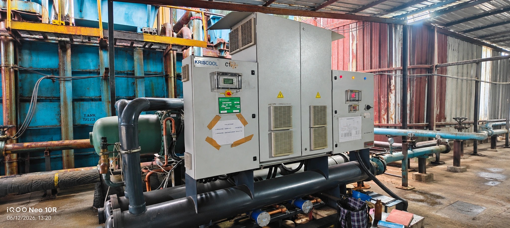
Key specifications and operating details for the KEHEMS KRISCOOL CRSW 2800 2 PE2 HE2
The rated cooling capacity is 258.8 TR at the stated rating conditions.
Rated absorbed power is 151.2 kW. This is electrical consumption at the rating point, not compressor motor nameplate power.
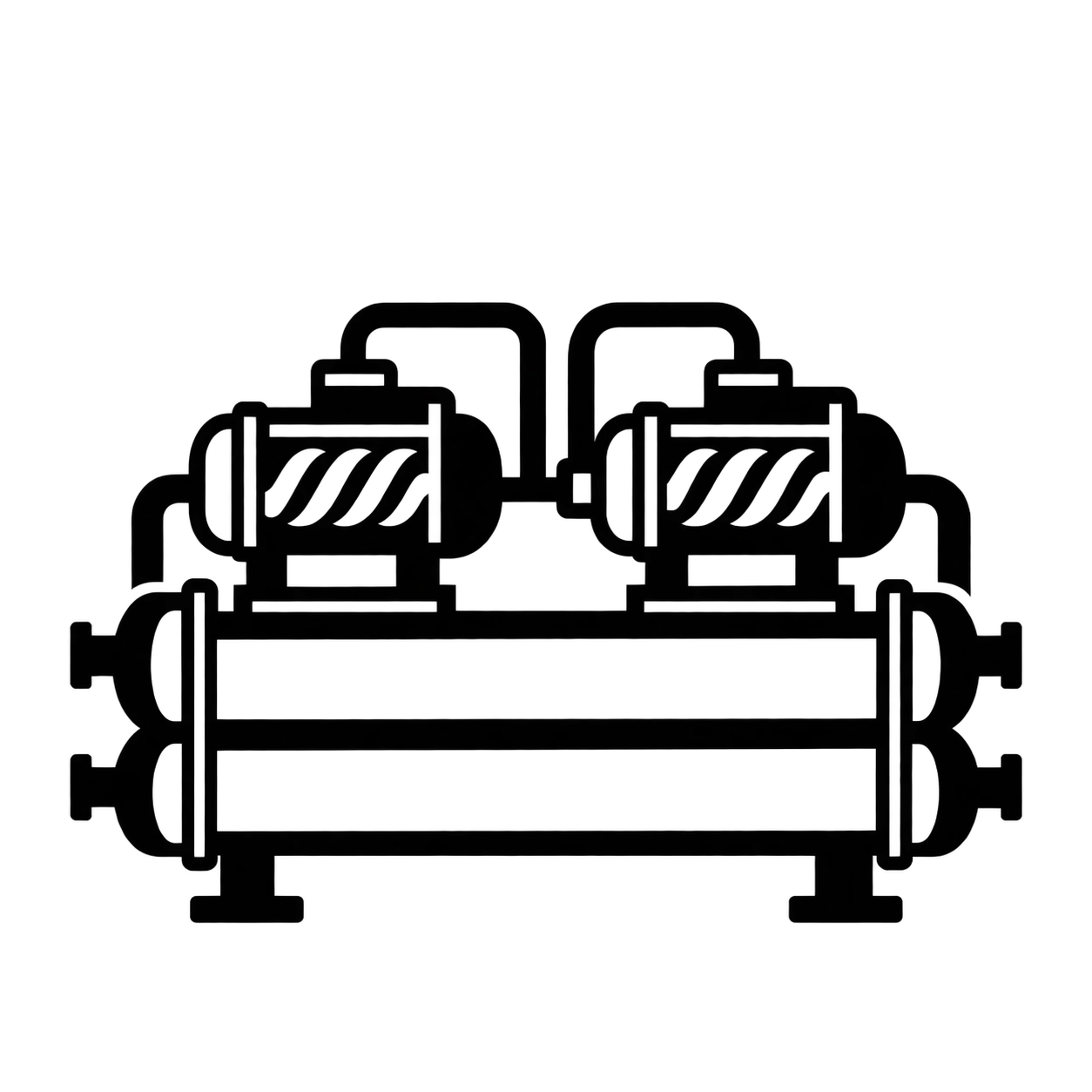
The unit has two independent R-134a circuits and two accessible semi-hermetic twin-screw compressors.
The operating weight is 5,535 kg; empty weight is 5,020 kg.