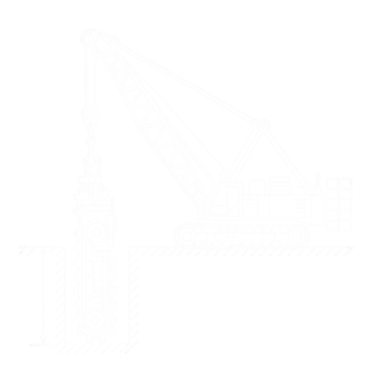
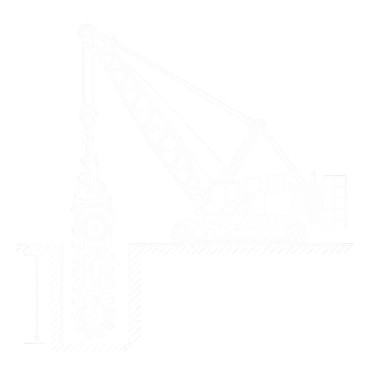
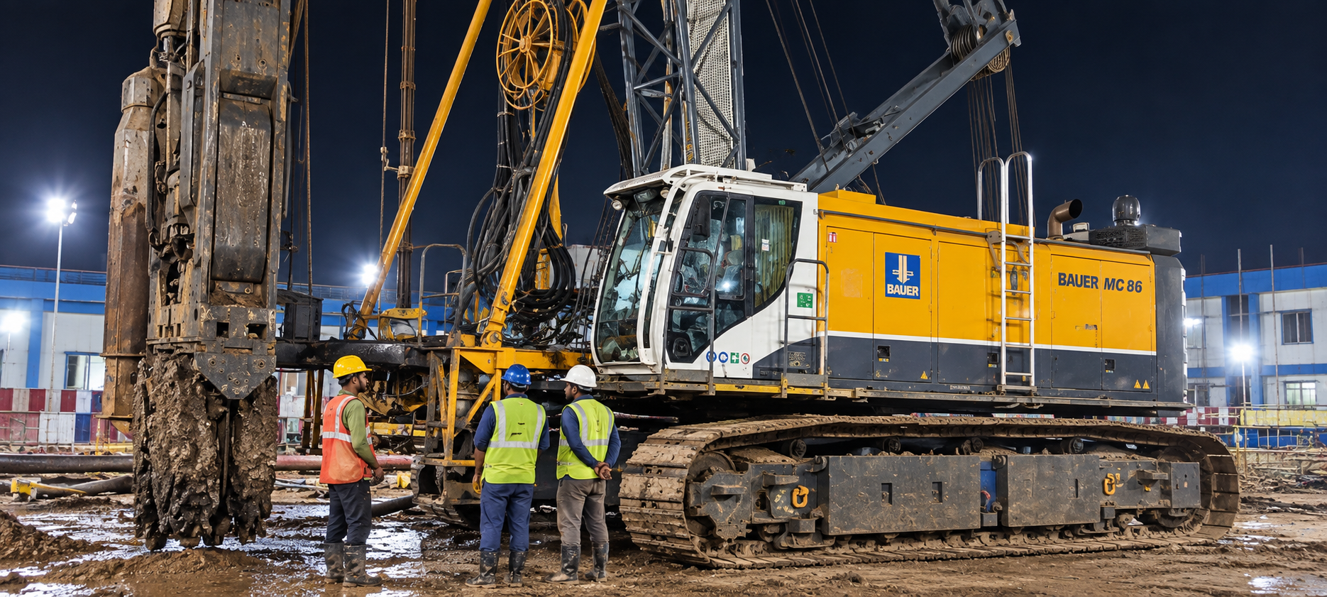
Bauer MC 86 duty-cycle crane in trench-cutter configuration
BAUERTrench Cutter Configuration

Bauer MC 86 Duty-Cycle Crane – Trench Cutter Configuration

The trench-cutting setup uses the Bauer MC 86 duty-cycle crane as the base carrier together with a Bauer Trench Cutter BC and an HTS or HDS hose-management system. The carrier and cutter-system values are shown separately because depth, load and weight depend on the selected setup.

Base carrier icon
Base CarrierMC 86
Cutting depth icon
Max Cutting Depth (HDS 100)100 m
Operating weight icon
Carrier Operating WeightApprox. 105 t
Engine icon
Engine FamilyCAT C18
Fuel tank icon
Diesel Tank1,000 L
Hydraulic pressure icon
Hydraulic Pressure320 bar

Key Highlights

Base carrier icon
Base Carrier

MC 86 duty-cycle crane

Engine icon
Engine Family

CAT C18 diesel

Engine output icon
Nominal Engine Output

570 / 563–576 / 470 kW (configuration-dependent)

Engine speed icon
Engine Speed

1,850 rpm

Diesel tank icon
Diesel Tank

1,000 L

Hydraulic tank icon
Hydraulic Tank

1,000 L

Hydraulic pressure icon
Hydraulic Pressure

320 bar

Hydraulic flow icon
Main Duty Circuits

2 × 430 L/min

Winch line pull icon
Hoisting Winch Pull

250 kN each

Rope speed icon
Max Rope Speed

94.3 m/min (hoisting)

Operating weight icon
Operating Weight

Approx. 105 t

Travel speed icon
Travel Speed

Approx. 1.25 km/h

Track shoe icon
Track Shoe Width

900 mm

Track width icon
Extended Track Width

4,160 mm

Cutting depth icon
Max Cutting Depth (HDS 100)

100 m

Specifications

Bauer MC 86 carrier specifications and trench-cutting options

CARRIER & ENGINE

  • Base CarrierBauer MC 86 duty-cycle crane
  • Engine FamilyCAT C18 diesel
  • Nominal Engine Output570 kW; 563/576 kW; 470 kW (engine/emissions configuration dependent)
  • Engine Operating Speed1,850 rpm
  • Diesel Tank Capacity1,000 L
  • Control SystemB-Tronic electronic control, monitoring & visualization
  • Operator CabFOPS-certified; heating & air conditioning

HYDRAULICS & WINCHES

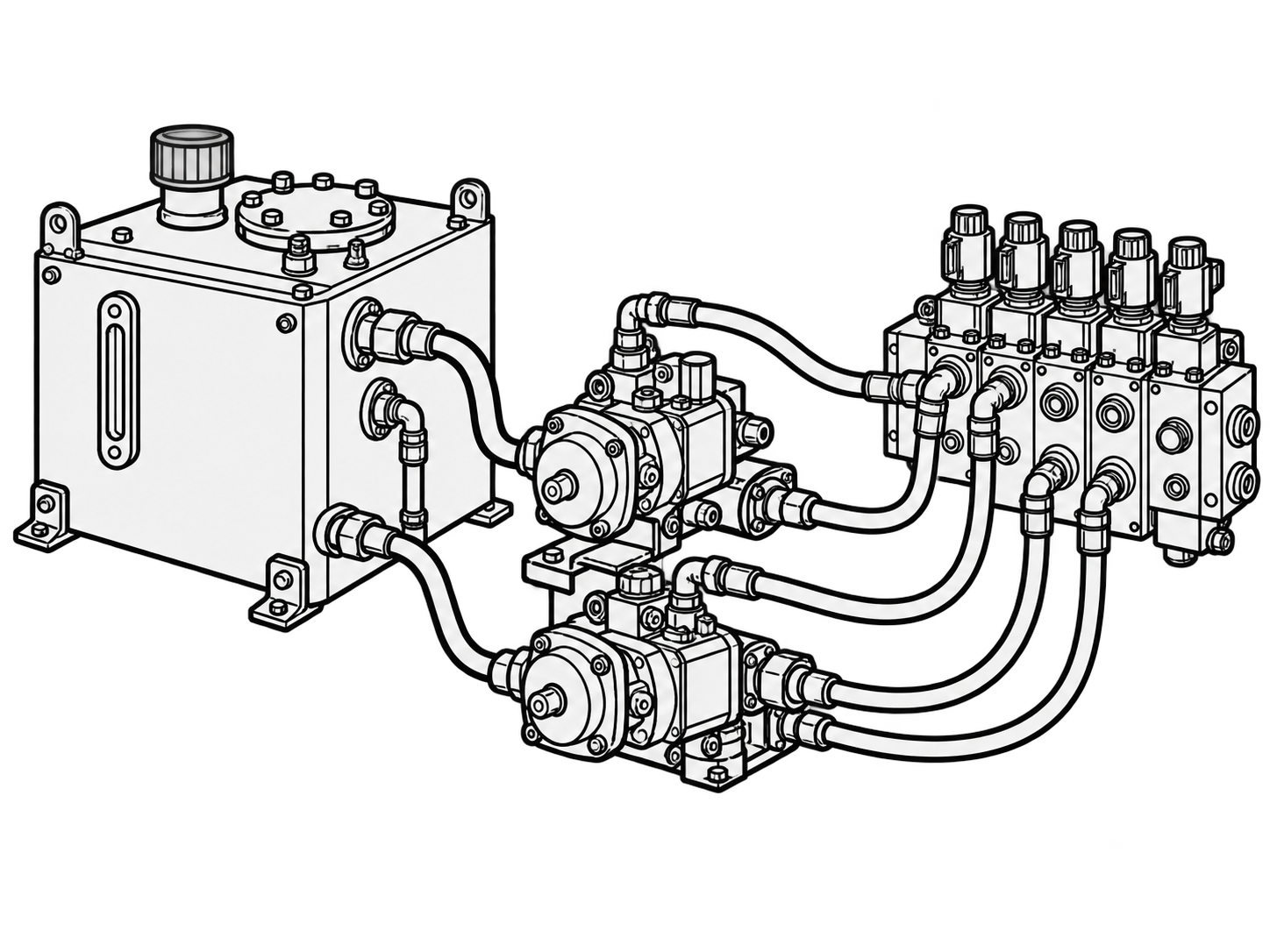
  • Main Duty-Cycle Circuits2 × 430 L/min
  • Main Winch Circuits2 × 400 L/min
  • Additional Circuit1 × 328 L/min
  • Swing-Gear Circuit1 × 204 L/min
  • Hydraulic Pressure320 bar
  • Hydraulic Tank Capacity1,000 L
  • Main Winch Line Pull250 kN each (hoisting); 300 kN each (free-fall)
  • Maximum Rope Speed94.3 m/min (hoisting); 103 m/min (free-fall)
  • Main Rope Diameter32 mm (hoisting); 34 mm (free-fall)
  • Boom HoistApprox. 120 kN; 22 mm rope

UNDERCARRIAGE & WEIGHT

  • Undercarriage TypeUW 120 BC
  • Crawler TypeB 8 B
  • Travel SpeedApprox. 1.25 km/h
  • Track Shoe Width900 mm
  • Track Width (Retracted / Extended)2,600 / 4,160 mm
  • Crawler Width (Retracted / Extended)3,500 / 5,060 mm
  • Crawler Length6,910 mm
  • Standard Counterweight2 × 12.5 t
  • Maximum Counterweight + Central Ballast40 t + 4 t
  • Transport Base-Machine Weight75 t with UW 120 BC
  • Carrier Operating WeightApprox. 105 t in the stated carrier setup

TRENCH-CUTTING SYSTEM

  • System ArchitectureMC 86 carrier + Bauer Trench Cutter BC + HTS/HDS hose system
  • MC 86 Carrier RoleBoom, winches, hydraulic circuits, crawler undercarriage & controls
  • Cutter AttachmentBauer Trench Cutter BC
  • Cutter FunctionPerforms trench excavation
  • Hose ManagementHTS (Hose Tensioning System) / HDS (Hose Drum System)
  • Total System WeightDepends on carrier, cutter, hose system & ballast configuration

DEPTH & HOSE-SYSTEM OPTIONS

  • HTS 38Hose Tensioning System · 38 m maximum cutting depth · Load: 40 t
  • HTS 50Hose Tensioning System · 50 m maximum cutting depth · Load: 35 t
  • HDS 100Hose Drum System · 100 m maximum cutting depth · Load: 45 t
  • How to Read These ValuesOptions are not interchangeable; confirm the fitted machine's operating load chart
  • Selection RequirementCheck cutter, hose system, ballast and carrier setup together
Trench-cutter load note: The loads are 40 t with HTS 38, 35 t with HTS 50 and 45 t with HDS 100. Total cutter weight includes the cutter, guide frame and pulley block. Permissible operating load depends on the installed cutter, hose system, ballast and carrier setup.

Bauer MC 86 Maintenance Checklist

Daily checks · Cat C18 service intervals · Warning actions

Check the installed machine first. The engine-hour intervals apply only after confirming the Cat C18 serial prefix and oil-pan type. Hydraulic, winch, slew, travel, wire-rope and trench-cutter intervals depend on the exact machine and attachment configuration.

Before every shift

These operator checks do not replace competent-person or statutory inspections. If a stop-use condition is found, isolate the machine and obtain a documented release before return to service.

Engine and cooling

1

Oil, coolant and fuel

Check levels, caps, hoses and connections; let the engine cool where required.

Act if: level is out of range, fluid is contaminated or a leak is active.

2

Air intake

Inspect restriction indication, ducts, clamps and joints.

Act if: the intake is unsealed, damaged or restricted.

3

Cooling pack and fan

Inspect coolers, radiator, fan and guards; clear loose debris safely.

Act if: airflow is blocked, parts are damaged or overheating occurs.

4

Exhaust and aftertreatment

Check shields, mounts, connections and derate messages.

Act if: hot gas leaks, a shield is damaged or a derate persists.

5

Belts and electrical system

With engine isolated, inspect belts, batteries, cables and charging warnings.

Act if: a part is loose, damaged, overheating or arcing.

Hydraulics, winches and ropes

6

Hydraulic reservoir and cooling

Check level, oil condition, filter indication, breathers and cooler.

Act if: oil is low, contaminated or foamed, or a leak appears.

7

Hoses, tubes and cylinders

Inspect routing, clamps, reinforcement, rods, pins and fittings.

Act if: there is a pressure leak, exposed reinforcement, drift or damage.

8

Main winches and brakes

Inspect drums, guards, anchors and spooling; test only by approved procedure.

Act if: brakes slip, rope cross-spools or movement is uncontrolled.

9

Wire ropes and terminations

Inspect accessible wear zones, anchors, sheaves and drum seating.

Act if: a rope kinks, crushes, corrodes, breaks wires or jumps a groove.

10

Boom-hoist rope and sheaves

Inspect rope, drum, sheaves, guards, anchors and connections.

Act if: damage, loose retainers or abnormal movement is found.

Undercarriage, structure and controls

11

Crawler and travel drives

Inspect shoes, bolts, rollers, idlers, sprockets and low-speed response.

Act if: cracks, loose parts, misalignment or braking faults occur.

12

Slew bearing and drive

Check fasteners, lubrication, leakage, play and smooth movement.

Act if: play, noise, cracks or uncontrolled motion occurs.

13

Boom and connections

Inspect members, welds, pins, retainers and guy ropes.

Act if: cracking, deformation, missing retainers or strand damage appears.

14

Counterweight and access

Confirm locks and setup; inspect platforms, rails and steps.

Act if: ballast is wrong, a lock is missing or access is unsafe.

15

B-Tronic

Complete self-check; verify configuration, readings and event log.

Act if: a stop message or repeated fault remains.

16

Emergency stop and safety

Test by the approved procedure for the fitted boom and tool.

Act if: any protective function fails or is bypassed.

17

Cab and visibility

Check seat belt, visibility aids, horn, lights and communication.

Act if: visibility, warnings or cab condition are unsafe.

18

Attachment interface

Confirm tool identity, locks, pins, hoses, cables and ropes.

Act if: locking is incomplete or a connection is damaged.

19

Ground and exclusion zone

Check platform, edges, overhead hazards, path and barricades.

Act if: stability, clearance or exclusion-zone control is inadequate.

20

Record and release

Log hour meter, alarms, defects and corrective work.

Act if: a stop-use defect remains open or release is missing.
Cat C18 service by hour meter

Choose an interval to see the engine tasks. Complete earlier tasks cumulatively; calendar time or fuel use may trigger service sooner. Confirm the fitted engine and oil pan before using the 250- or 500-hour plan.

Engine levels and intake

Coolant and engine-oil levelsCheck
Air-cleaner indicator and precleanerInspect
PTO clutch and walk-aroundCheck

Fuel and weekly item

Fuel-water separator and tank sedimentDrain
Jacket-water heater, if equipped — weeklyCheck

The oil/filter task at 250 hours applies only to a confirmed shallow-pan C18. Initial valve-lash and rotator checks also depend on the installed oil-pan arrangement.

Oil, coolant and fuel

Engine-oil sample and oil/filter — shallow panSample / Change
Coolant Level 1 sample and SCAObtain / Test-Add
Primary separator element and secondary fuel filterReplace

Inspection and cleaning

Battery electrolyte and grounding studCheck / Inspect-Clean-Tighten
Crankcase breather and radiatorClean
Hoses and clampsInspect / Replace
Initial valve lash and rotators — shallow panCheck / Inspect

The oil/filter task at 500 hours applies only to a confirmed deep-pan C18. The 250-hour inspection tasks still apply where scheduled for the fitted engine.

Oil and coolant

Engine-oil sample and oil/filter — deep panSample / Change
Coolant Level 2 sample after new/refilled/converted systemObtain

Engine components

Belts, starter, turbocharger and water pumpInspect / Adjust-Replace
Initial valve lash and rotators — deep panCheck / Inspect

Electrical

Alternator — 2,000 hours or 1 yearInspect

Annual coolant

Coolant Level 2 sample — every yearSample

Cooling and fan drive

Aftercooler coreClean-Test
Coolant-temperature regulatorReplace
Vibration damperInspect
Fan-drive bearingLubricate
Speed sensorClean-Inspect

Engine condition

Driven equipmentCheck
Electronic unit injectorsCheck-Replace
EngineClean
Engine mountsInspect
Protective devicesCheck
Valve lashCheck
Valve rotatorsInspect

760,000 L fuel trigger

Fan-drive bearingReplace
Overhaul considerationsReview

Condition-based tasks

Battery and cables, coolant/ELC, air cleaner, fuel priming and storage itemsAs needed

These are engine tasks only. Do not transfer their hours to the MC 86 hydraulic, winch, travel or cutter systems.

Warning signs and first response

Stop and make safe for red conditions. Amber conditions require diagnosis before the affected function continues. A cleared display is not, by itself, a return-to-service decision.

RED

Engine oil pressure or shutdown

Immediate action: stop as soon as safe; check level and codes. Do not restart while the warning persists.

Risk if ignored: engine seizure, bearing damage or sudden power loss.

RED

Engine overheating

Immediate action: secure the load or tool if safe; shut down by approved procedure and inspect cooling components.

Risk if ignored: engine damage or shutdown during operation.

RED

Major hydraulic leak or pressure loss

Immediate action: stop motion, support equipment, isolate and depressurise by approved procedure. Never check a leak by hand.

Risk if ignored: uncontrolled movement or fluid-injection injury.

RED

Winch brake or free-fall fault

Immediate action: secure or lower the load or tool, quarantine the machine and arrange qualified service.

Risk if ignored: dropped load or tool.

RED

Rope damage or mis-spooling

Immediate action: stop winch operation until rope and terminations are inspected to approved criteria.

Risk if ignored: rope failure or dropped equipment.

RED

Safety fault or structural damage

Immediate action: isolate the machine; have the fault or damage assessed and documented before release.

Risk if ignored: loss of a protective function or structural failure.

AMBER

Filter restriction or contamination

Action: check filter indication, oil condition and temperature; service to the approved trigger.

Risk if ignored: hydraulic wear or overheating.

AMBER

New noise, vibration or heat

Action: stop the affected function and inspect oil, leaks, mountings and mechanical condition.

Risk if ignored: bearing, gear or hydraulic damage.

AMBER

Repeated B-Tronic fault

Action: record the exact code, hour meter and configuration; resolve the cause before continuing.

Risk if ignored: lost monitoring or unexpected derate.

SERVICE

Service due or service information unavailable

Action: open the service work order and use the instructions for the installed carrier, engine and attachment.

Risk if ignored: wrong interval, lubricant, part or incomplete service record.

Frequently Asked Questions

Common questions about the Bauer MC 86 trench-cutting configuration

The MC 86 is a duty-cycle crane used as the base carrier. In a trench-cutting configuration, it works with a Bauer Trench Cutter BC and a suitable HTS or HDS hose-management system.

HTS means Hose Tensioning System and HDS means Hose Drum System. Maximum cutting depths are 38 m with HTS 38, 50 m with HTS 50 and 100 m with HDS 100. These names identify hose-system options, not cutter models.

No. The 100 m maximum cutting depth applies to the HDS 100 setup. Achievable depth and permissible load depend on the cutter, hose system, ballast and carrier setup.

Cutting width varies with the fitted Bauer Trench Cutter BC configuration.

No universal trench-cutter system weight should be inferred from that figure. The approximate 105 t value describes a particular MC 86 carrier setup with HD undercarriage, 900 mm track shoes, two hoist winches, 25 t counterweight, an 18.4 m basic boom and a 100 t hook block.